Introduction
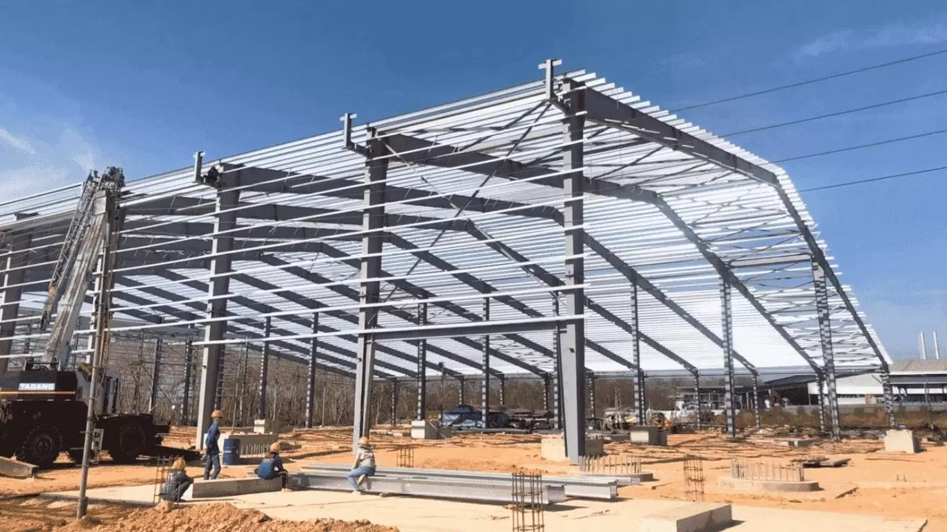
A steel truss is one of the most structurally efficient load-carrying systems in civil and industrial engineering. By converting applied loads into pure axial forces — tension and compression — distributed across a triangulated network of members, a truss achieves a strength-to-weight ratio that no equivalent solid beam can match at the same span. It is this intrinsic efficiency that makes steel trusses the structural solution of choice for aircraft hangars, long-span industrial roofs, stadium canopies, bridge decks, transmission towers, and offshore platforms worldwide.
Yet despite their prevalence, most publicly available information on steel trusses stops at the level of naming truss types and listing generic applications. For structural engineers, project developers, EPC contractors, and procurement teams working on large-scale industrial projects, that level of information is insufficient. Specifying, designing, fabricating, and erecting steel trusses at industrial scale demands a deep understanding of structural mechanics, member design, connection detailing, material standards, fabrication quality control, erection sequencing, and total cost of ownership.
This guide — produced by Pebsteel, one of Asia’s largest integrated steel structure manufacturers — addresses all of those dimensions. It is written specifically for B2B decision-makers who need accurate, engineering-level information to make informed specification and procurement decisions.
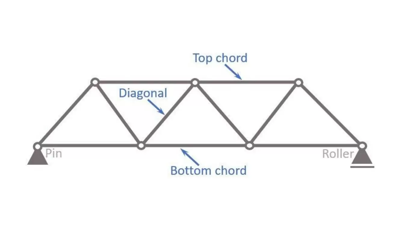
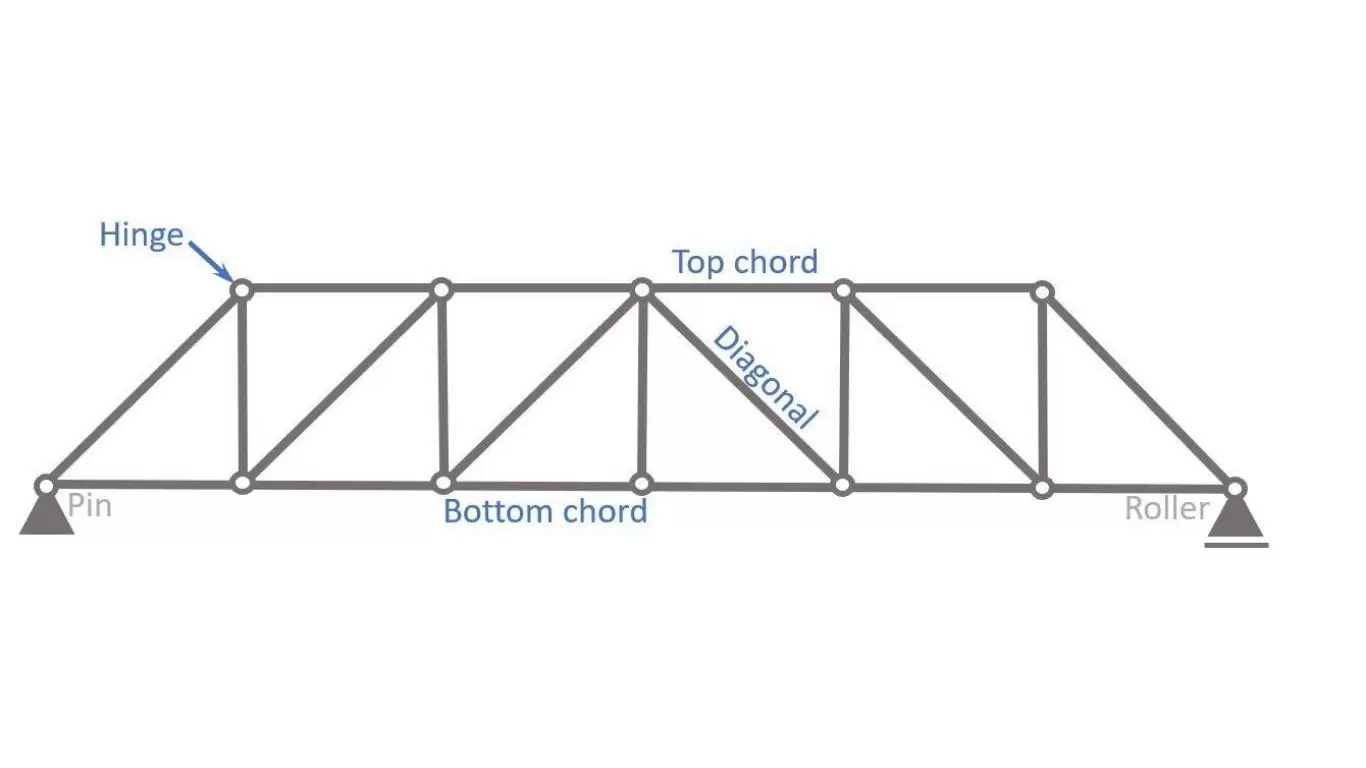
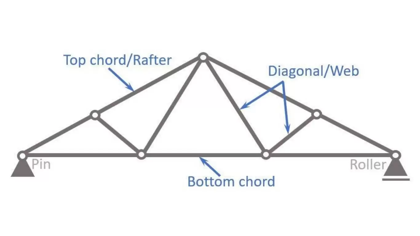
1. What Are Steel Trusses?
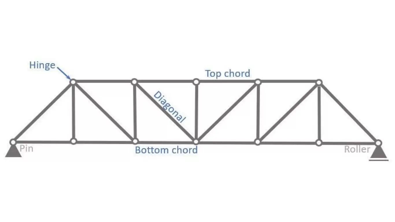
In structural mechanics, a truss is a framework of straight members joined at nodes (also called joints or panel points), arranged in a triangulated pattern such that, under idealised pin-joint assumptions, every member carries only axial force — either tension or compression — with no bending or shear. This idealisation, while not perfectly realised in fabricated structures, is the fundamental property that makes trusses so material-efficient: every part of every member is fully stressed in the same direction (tension or compression), eliminating the inherently wasteful stress gradient that occurs across the depth of a solid beam in bending.
Engineering Definition
A truss satisfies the following assumptions:
- Members are connected by pin joints (ideal condition)
- Loads are applied only at joints
- Members carry only axial tension or compression
👉 This eliminates bending moments, making trusses significantly more efficient than beams.
The Triangulation Principle — Why It Matters for Engineers
A triangulated system is geometrically stable under any pattern of loading applied at the nodes. A rectangular (quadrilateral) panel, by contrast, is a mechanism — it can deform under lateral load without any member failing. By subdividing the structure into triangles, the truss eliminates this mechanism behaviour and creates a rigid, stable framework. Every additional triangular panel added to the basic triangle increases the member count by two (one diagonal and one vertical or chord extension), maintaining the determinacy condition:
m = 2j − 3 (statically determinate planar truss: m = members, j = joints)
When m > 2j − 3, the truss is statically indeterminate (hyperstatic). Continuous chord connections, rigid gusset plates, and secondary bending in welded connections all introduce indeterminacy into real fabricated trusses. Modern structural analysis uses finite element method (FEM) software — STAAD.Pro, SAP2000, RFEM — to capture these real behaviour effects, particularly for heavy-load and long-span trusses where secondary bending moments at welded nodes are non-negligible.
Why triangles?
- A triangle is the simplest stable polygon
- It cannot change shape without changing member length
👉 This is the core principle behind truss stability.
Force Distribution in a Steel Truss
Under vertical gravity loads, the top chord of a simply-supported truss is in compression (like the top flange of a beam) and the bottom chord is in tension (like the bottom flange). The internal web members — diagonals and verticals — carry shear as axial forces. The magnitude of these forces depends on truss geometry, panel arrangement, and load position.
The method of joints and the method of sections are the classical hand-calculation tools for determining member forces in determinate trusses. For complex trusses and multi-load-case analyses, matrix stiffness methods are used exclusively in modern practice. Understanding the force flow allows the engineer to optimize member cross-sections: tension members can use slender, high-strength sections (angles, flats, round bars, or T-sections); compression members require stockier sections with adequate cross-sectional area and slenderness control to prevent buckling.
When a load is applied:
- Load transfers to joints
- Members experience axial forces
- Forces are transmitted to supports
👉 Efficient load path = lower stress concentration
Material Efficiency
Compared to solid beams:
- Steel usage reduced by 20–40%
- Self-weight reduced significantly
- Transportation and erection easier
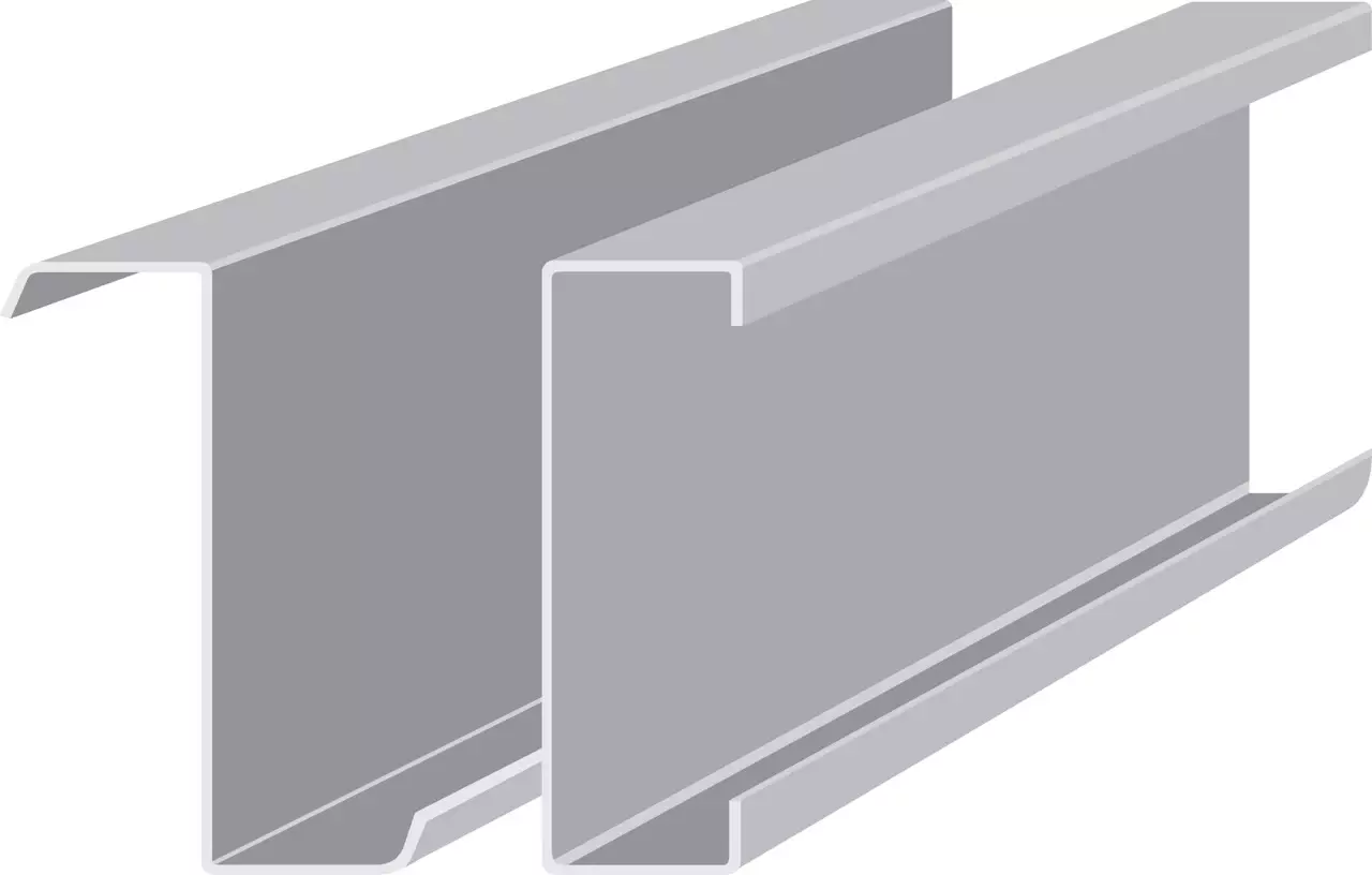
More about our PebHybrid®, one of the standard frames for Pre-engineered Buildings that is developed by Pebsteel. The rafters of PebHybrid® are a truss structure from 2 Omegas cold-formed sections (upper and lower) connected with the square tubes’ hollow sections by bolts.
2. Types of Steel Trusses: Classification by Configuration
Steel trusses are classified by the geometric arrangement of their chord and web members. Each configuration has been developed to optimise material efficiency, fabrication economy, or load-carrying behaviour for specific span ranges and load patterns. The following classification covers all major types used in industrial and commercial construction.
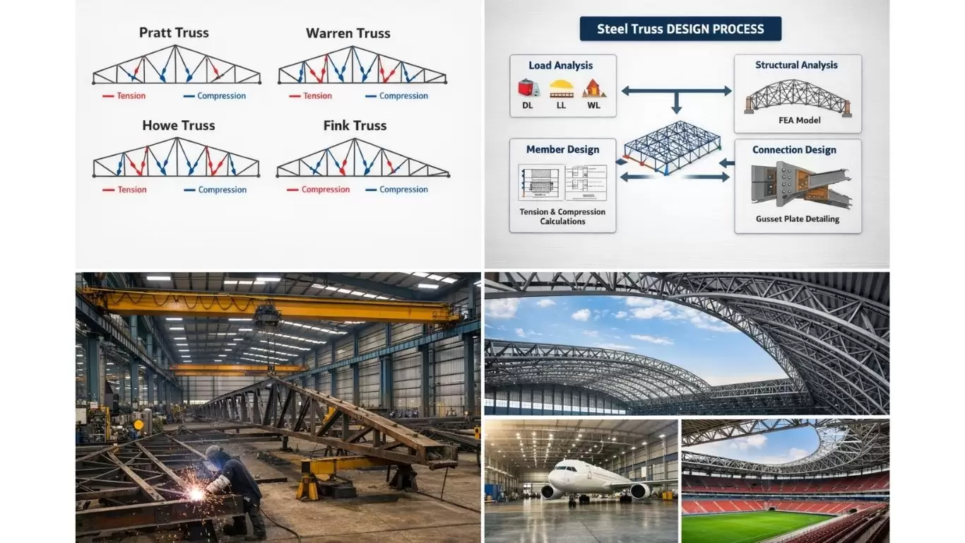
Pratt Truss (N-Configuration)
The Pratt truss, developed by Thomas and Caleb Pratt in 1844, remains one of the most widely used configurations for long-span industrial roof and bridge structures. Its defining characteristic is that the diagonal web members slope toward the centre of the span — under downward gravity loads, these diagonals are in tension and the vertical web members are in compression.
This force distribution is structurally efficient because tension members can be designed as lighter, slender elements without the buckling constraint that governs compression members. For gravity-dominated loading (warehouses, factories, logistics facilities), the Pratt truss typically delivers the lowest steel weight per unit of covered area. Typical application span: 20–100 m. Pitch: commonly 1:10 to 1:5. Depth-to-span ratio: typically 1:8 to 1:12.
Characteristics:
- Diagonals in tension
- Vertical members in compression
Engineering Advantage:
- Efficient for gravity loads
- Reduced buckling risk
👉 Common in industrial roofs and bridges
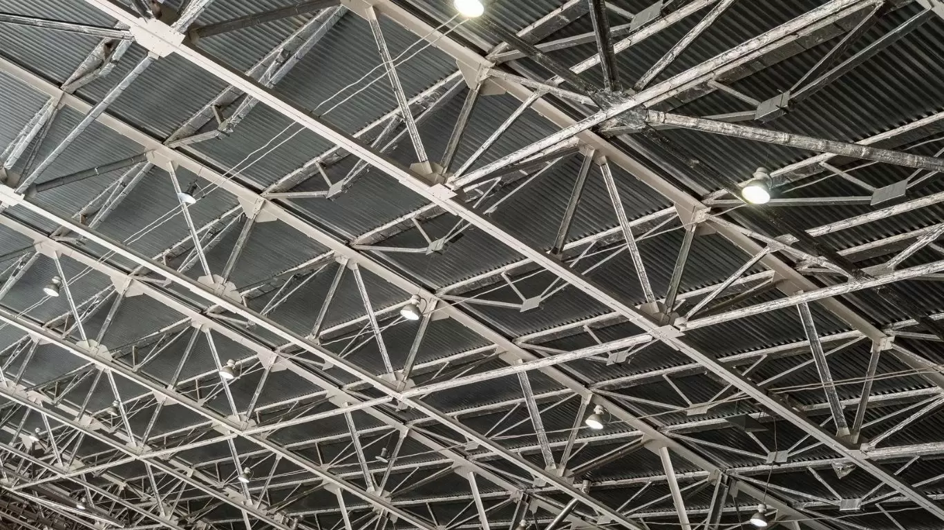
Warren Truss (W / Equilateral Configuration)
The Warren truss uses diagonal members alternating in compression and tension with no vertical members (in the pure form) or with added verticals at panel points (modified Warren). All diagonals form equilateral or isosceles triangles, giving the truss excellent shear distribution and a regular, repeating geometry that simplifies fabrication.
The Warren truss is preferred when node spacing must accommodate purlin or service attachment points at regular intervals. Modified Warren trusses (with added verticals) are used to provide intermediate support nodes without changing the diagonal force pattern significantly. Span range: 20–100 m for roof structures; up to 300+ m in large-scale bridge and long-span structures. The Warren configuration is also standard for horizontal trusses in crane girder assemblies and gantry structures.
Characteristics:
- Repeating equilateral triangles
- No vertical members
Performance:
- Uniform force distribution
- Suitable for evenly distributed loads
Howe Truss
The Howe truss reverses the Pratt diagonal orientation — diagonals slope outward from the centre, putting them in compression under gravity loads while vertical members carry tension. This makes the Howe truss less material-efficient than the Pratt for gravity-dominated loading because the longer diagonal members now carry compression and require bulkier cross-sections to prevent buckling. The Howe truss is therefore less common in modern industrial roof design but retains application in situations where uplift load reversal is critical, since under net uplift the Howe diagonals become tension members.
Characteristics:
- Diagonals in compression
- Verticals in tension
Limitation:
- Compression members prone to buckling
Fink Truss
The Fink truss subdivides the top chord into shorter compression panels by introducing a W-shaped (or fan-shaped) web arrangement with shorter, more economical sub-members. It is highly material-efficient for steep-pitched roofs (pitch > 1:4) because the shorter members have lower slenderness ratios and therefore higher compression capacity. The Fink truss is predominantly used for residential and light commercial applications with spans of 8–20 m, but modified Fink and fan truss configurations are also applied in light industrial buildings.
Characteristics:
- Subdivided triangular pattern
- Lightweight
👉 Ideal for:
- Roof structures
- Medium spans
North Light Truss (Saw-Tooth / Shed Truss)
The North Light truss is an asymmetric profile with a steep pitch on one side (typically facing north or north-east in the Northern Hemisphere) and a shallower pitch on the other. The steep face incorporates glazing to introduce diffuse natural daylight without direct solar gain. North Light trusses are among the oldest and most practical designs for industrial workshop buildings requiring daylighting without air conditioning penalties. Modern energy analysis using dynamic thermal simulation (e.g., EnergyPlus or IES-VE) is recommended to quantify the net operational carbon impact in specific climatic contexts.
Vierendeel Truss
The Vierendeel truss departs fundamentally from the triangulation principle: it has no diagonal web members, with rectangular panels formed by vertical members rigidly connected to the chords. Load is transferred by bending moments at the rigid joints, not by triangulated axial forces. Vierendeel trusses are statically indeterminate and require moment-resisting connections — typically full-penetration welded joints with significant joint reinforcement.
The engineering case for a Vierendeel truss is aesthetic and functional: the open rectangular web allows architectural services, penetrations, or glazed infill panels without the diagonal members that obstruct visual and physical access in a conventional triangulated truss. They are used in bridge pedestrian walkways, architect-led commercial buildings, and transfer floors in high-rise structures. The trade-off is significantly higher steel weight (typically 40–80% heavier than an equivalent Warren truss) and higher fabrication cost due to moment-resisting welded connections.
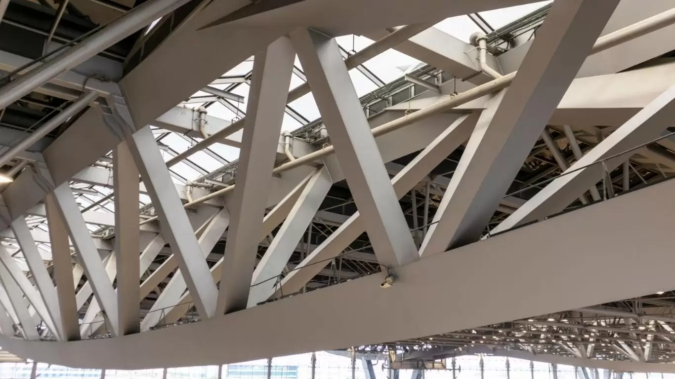
Space Frame (Three-Dimensional Truss)
A space frame extends the planar truss concept into three dimensions by interconnecting multiple planar trusses or by using a three-dimensional node-and-strut system (typically ball-and-socket or welded ring nodes) to create a doubly-curved or flat grid structure. Space frames are the structural solution for extreme clear spans — aircraft hangars (60–200 m span), exhibition halls, stadium roofs, airport terminals — where the biaxial load distribution allows highly efficient member sizing.
The most common space frame configurations are the square-on-square offset grid and the triangulated-on-triangulated grid. Member sections are typically circular hollow sections (CHS) for their isotropic bending resistance and superior node weld geometry. Space frame design is always performed using full 3D FEM analysis; simplified hand methods are not applicable at the span scales where space frames are economically justified.
|
Truss Type |
Typical Span | Dominant Force in Diagonals |
Primary Industrial Application |
| Pratt (N) | 20–100 m | Tension | Warehouse, factory, logistics roof |
| Warren / Modified Warren | 20–100 m | Alternating T/C | Long-span roof, crane girder horiz. truss |
| Howe | 10–30 m | Compression | Uplift-critical; bridge structures |
| Fink / Fan | 8–20 m | Compression (top chord panels) | Light industrial, residential |
| North Light / Saw-tooth | 10–35 m per bay | Mixed | Daylighting industrial workshops |
| Vierendeel | 10–50 m | Bending (no diagonals) | Architectural; transfer floors |
| Space Frame (3D) | 40–200+ m | Axial (3D distribution) | Hangars, stadiums, airports, expo halls |
3. Steel Truss Member Design: Chord and Web Member Sizing and Code Checks
Structural design of steel truss members goes well beyond computing member forces. Each member must be checked against multiple failure criteria under the governing design code. This section presents the key design checks for chord and web members.
Tension Member Design
Bottom chord members (and tension diagonals in Pratt trusses) carry pure tensile force. The design check compares the factored tensile demand to the section’s tensile capacity. Under AISC 360 (LRFD approach):
φ_t × P_n = min(φ_t × F_y × A_g; φ_t × F_u × A_e) φ_t = 0.90 (yielding); 0.75 (fracture)
The effective net area Ae accounts for shear lag at bolted or welded connections — a critical reduction factor where only part of the cross-section is connected (e.g., one leg of an angle connected to a gusset plate). Under EN 1993-1-1, the net section resistance is:
N_t,Rd = min(A × f_y / γ_M0; 0.9 × A_net × f_u / γ_M2)
For long tension members (particularly bottom chord members spanning between panel points), the engineer must also verify that the member does not sag excessively under self-weight and that it does not have unacceptable residual deflection from erection. Circular hollow sections (CHS) and rectangular hollow sections (RHS) are increasingly used for bottom chord members in architecturally exposed structures because they present a clean, compact profile.
Compression Member Design — The Buckling Critical Case
Top chord members and compression diagonals in Howe or reversing-load trusses are governed by column buckling. The effective length factor (K) for a truss chord or web member depends on the restraint provided at the panel point connections. For chord members:
- In-plane buckling: The effective length is the panel length between node connections (L_panel). If the top chord is continuously connected to purlins, in-plane buckling is inhibited between purlin points.
- Out-of-plane buckling: The effective length is the distance between lateral bracing points. In roof trusses, purlins connected to the top chord provide lateral restraint; the bottom chord must be braced at intervals by plan bracing or by subsidiary bracing members.
For compression web members (verticals and diagonals), effective length assumptions per AISC Design Guide 9 and EN 1993-1-1 Annex A depend on end-connection rigidity. For welded gusset plate connections with moderate in-plane rigidity, an effective length factor of K = 0.85L (in-plane) and K = 1.0L (out-of-plane) is commonly used, though more precise analysis is warranted for heavy-load applications.
The column buckling capacity in AISC LRFD:
φ_c × P_n = φ_c × F_cr × A_g where F_cr depends on λ_c = (KL/r_min) × √(F_y / π²E)
Under EN 1993-1-1, the buckling resistance is:
N_b,Rd = χ × A × f_y / γ_M1 χ = reduction factor from buckling curve (a, b, c, or d)
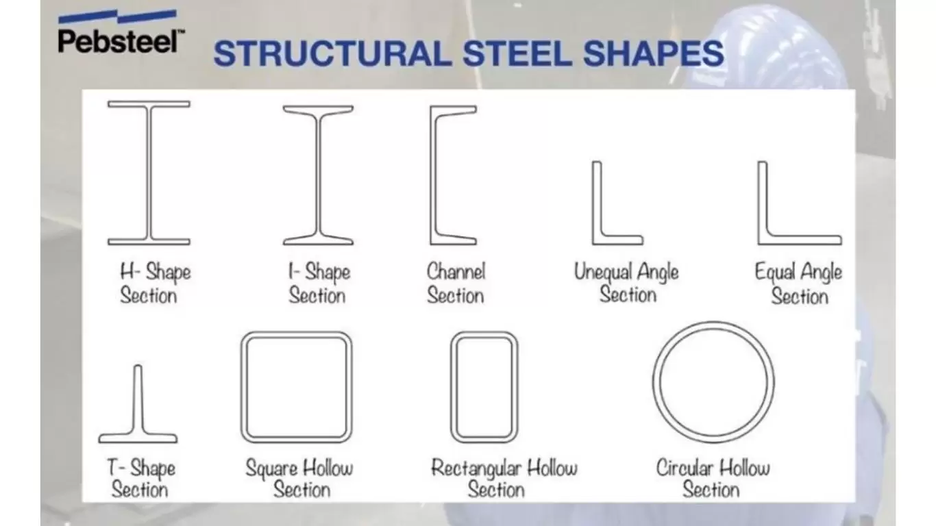
Section Selection for Truss Members
The cross-section type selected for each member role affects fabrication cost, connection detailing complexity, and structural efficiency:
|
Member Role |
Common Sections | Structural Advantage |
Fabrication Note |
| Top chord (compression) | T-section (WT), RHS, 2×angle back-to-back | Stem of WT provides direct weld surface for web members | WT cut from W-section; efficient for welded gussets |
| Bottom chord (tension) | Flat bar, L-section, RHS, CHS | Full cross-section effective in tension; CHS aesthetically clean | CHS nodes require accurate cutting; open sections simpler |
| Diagonal web (tension) | Single angle, rod, flat, CHS | High slenderness acceptable in tension; low section cost | Angle welded or bolted to gusset plate at each end |
| Diagonal web (compression) | Double angle, T-section, RHS | Higher second moment of area resists buckling; lower KL/r | Back-to-back angles require intermittent ties; RHS cleanest |
| Vertical web | Single or double angle, T-section, RHS | Selection depends on force magnitude and connection geometry | Hangers (tension verticals) can be simple rods or angles |
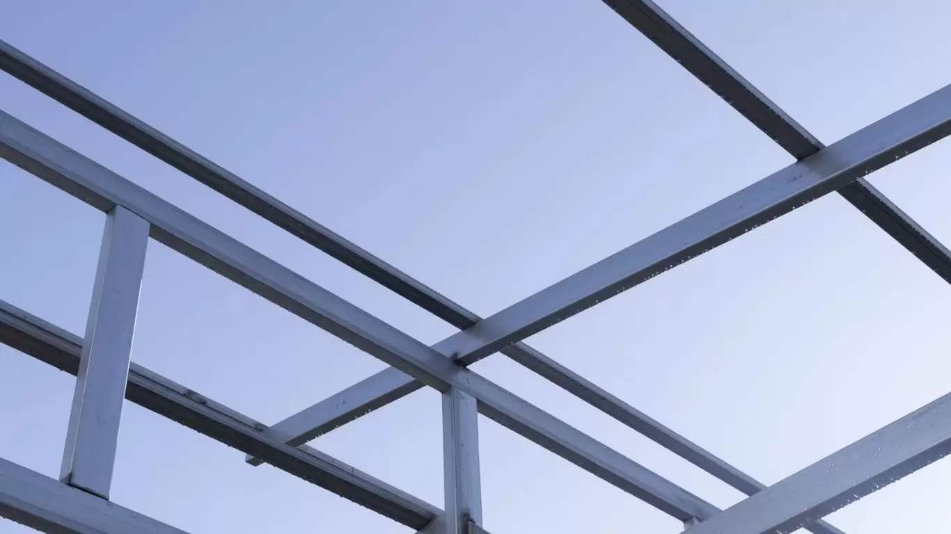
4. Truss Connection Design: Gusset Plates, Welded Nodes, and HSS Joints
Connection design is frequently cited as the most complex and time-intensive aspect of steel truss engineering. It is also the dimension most consistently missing from B2B-facing truss guides. In practice, connection design often governs member selection — the required gusset plate geometry, weld length, or bolt group size may necessitate a larger member section than the pure force calculation demands. Understanding connection fundamentals prevents costly field RFIs and redesigns.
Gusset Plate Connections (Open Section Trusses)
For trusses fabricated from angles, T-sections, or flat bars, the gusset plate is the primary connecting element at each panel point. The gusset plate receives all converging web members and connects them to the chord member via welds or bolts. Gusset plate design must check:
- Whitmore section in tension: The effective width of the gusset plate in tension at the end of the member force introduction zone, calculated at 30° spread from the first to last weld or bolt. Net section yielding and fracture of this Whitmore width governs gusset tension capacity.
- Block shear failure: Combined shear yielding and tensile fracture along the weld lines in the gusset plate or chord flange. Checked per AISC 360-22 Section J4.3 or EN 1993-1-8 Section 3.10.2.
- Gusset plate buckling (compression struts): Where a diagonal introduces significant compression into the gusset, the free length of unsupported plate between the member end and the chord face must be checked for plate buckling. Stiffeners may be required.
- Weld design: All fillet or CJP (complete joint penetration) welds are designed for the vector sum of shear forces in both axes plus any moment arising from eccentricity in the load path. Per AWS D1.1 or EN ISO 15614-1.
Welded Hollow Section (HSS/CHS) Node Joints
For trusses fabricated from hollow structural sections — circular (CHS) or rectangular (RHS/SHS) — connections are typically direct-welded without gusset plates, with web members welded directly to the chord face. These ‘tubular joints’ or ‘K-joints’, ‘T-joints’, ‘X-joints’ or ‘KT-joints’ (depending on configuration) develop complex stress fields in the chord wall at the weld toe.
Tubular joint resistance is governed by three failure modes checked per AISC 360-22 Chapter K or EN 1993-1-8 Chapter 7:
- Chord face plastification: The chord wall deforms plastically under the local force from the brace member. Governed by chord wall thickness t₀ and diameter D₀ (for CHS) or width b₀ (for RHS).
- Chord shear failure: The cross-section of the chord at the joint shears under the combined shear from brace members and chord axial force.
- Brace member failure (effective width): For RHS-to-RHS joints, only part of the brace member width is effective in transmitting force to the chord. The effective width depends on the b₁/b₀ ratio.
Practical rules to avoid expensive joint reinforcement: maintain brace-to-chord width ratio (β = b₁/b₀ or d₁/d₀) ≥ 0.5; keep chord wall slenderness (b₀/t₀ or D₀/t₀) below 25–30; maintain gap g between tension and compression brace weld toes ≥ the larger of t₁ or t₂.
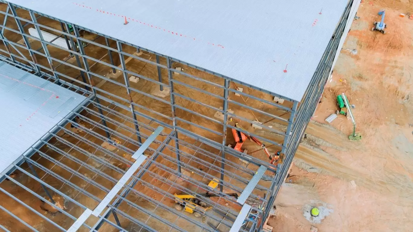
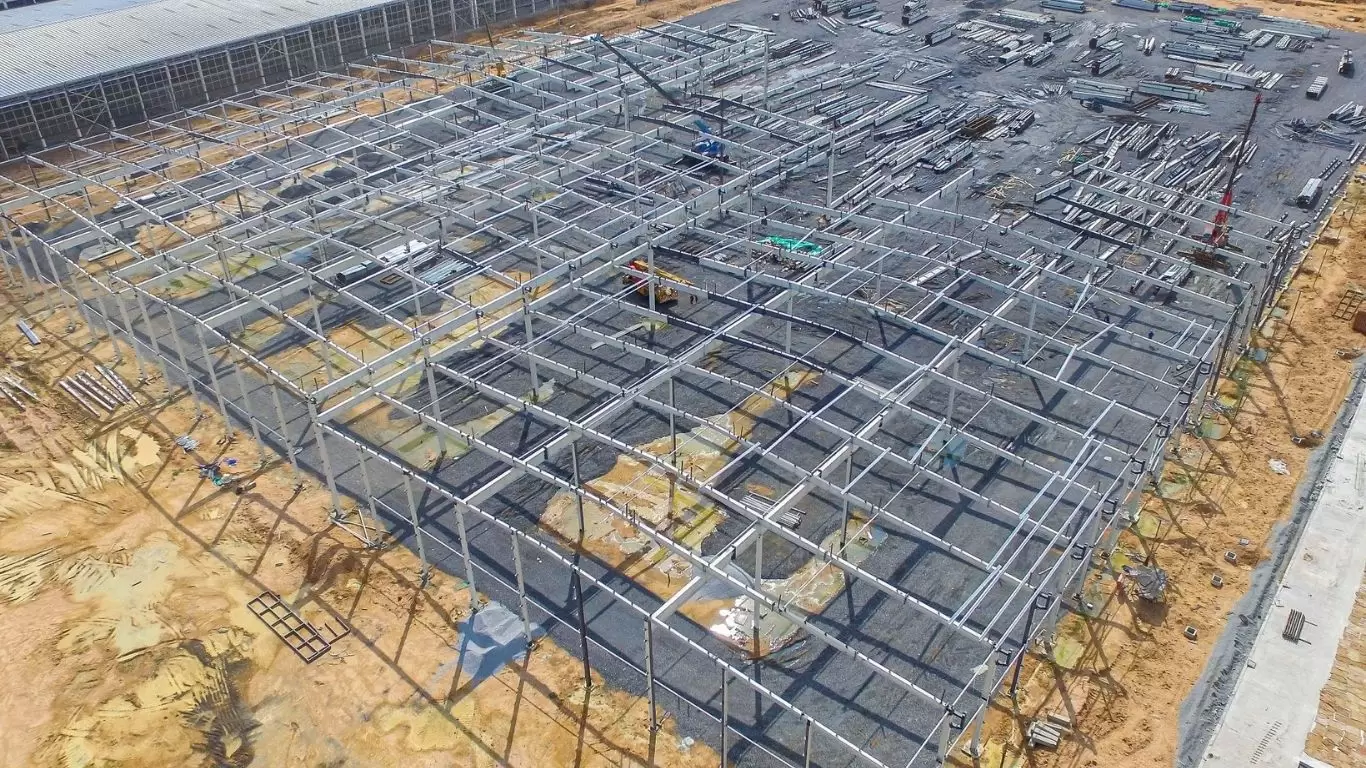
5. Steel Truss Fabrication: Processes, Camber, and Quality Standards
The quality of a fabricated steel truss is determined long before it leaves the factory. Understanding fabrication processes, dimensional tolerances, camber requirements, and quality inspection holds is essential for B2B procurement teams specifying large-scale truss packages.
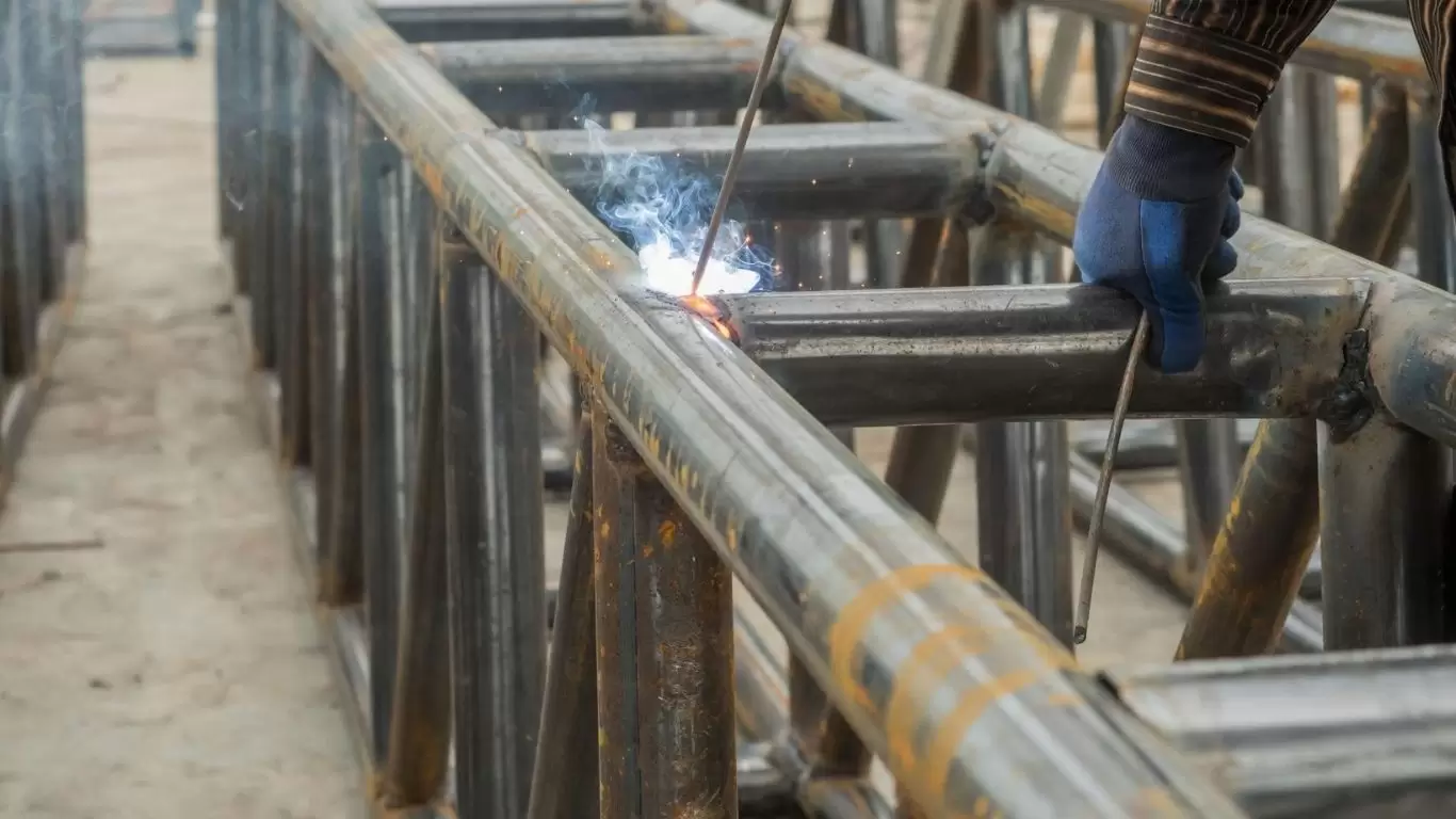
Fabrication Process Overview
- Plate and section cutting: CNC plasma or laser cutting of gusset plates, chord sections, and web members to dimensional tolerance ±1 mm on cut lengths.
- Jig assembly: Trusses are assembled in purpose-built floor or table jigs that hold chord members and web members in their theoretical geometry. Jig accuracy directly determines as-fabricated geometric accuracy.
- Fit-up and tack welding: Web members are fitted to chords and gussets, tack-welded in position, and verified dimensionally before full weld runs are applied.
- Full welding: Fillet welds and CJP welds applied per the approved Welding Procedure Specification (WPS) in accordance with AWS D1.1 or EN ISO 15614-1. Automated welding (robot GMAW or submerged arc) is used where joint geometry allows.
- Non-destructive testing (NDT): Visual inspection (VT) of all welds; magnetic particle testing (MT) of tension chord-to-gusset welds; ultrasonic testing (UT) of CJP welds at critical connections, per the approved Inspection and Test Plan (ITP).
- Shot blast and prime: Sa 2.5 blast cleaning followed by zinc-rich epoxy primer to specified DFT.
Precambering: The Critical Deflection Management Tool
A long-span truss under dead load will deflect downward. If no compensation is applied, the installed truss will sag from its intended straight profile, creating drainage problems on roofs, visual imperfection, and potential fitment issues with wall panels and cladding at the eave.
Precambering (cambering) involves fabricating the truss with a pre-set upward bow opposite to the anticipated dead load deflection. When the truss is loaded with its dead load in service, this camber is consumed and the truss member approaches its designed straight geometry under full dead load. The camber magnitude is typically 75–100% of the calculated dead-load deflection for roof trusses.
Camber is introduced in the fabrication jig by deliberately offsetting the chord panel points upward from their theoretical straight positions. The fabricator must maintain panel point positions to ±2 mm from the cambered geometry to ensure that the live-load deflection envelope and the drainage slope targets are achieved.
Dimensional Tolerances — AISC vs EN 1090
|
Dimension |
AISC Code of Standard Practice |
EN 1090-2 EXC2 |
| Overall truss length | ±3 mm for L ≤ 9 m; ±5 mm for L > 9 m | ±L/1000 but ≤ ±10 mm |
| Truss depth at midspan | ±3 mm | ±3 mm |
| Bow / sweep (lateral) | L/1000 ≤ 10 mm | L/750 |
| Camber deviation (from specified) | ±6 mm or ±L/1000 | ±L/500 |
| Node/panel point position | ±3 mm | ±3 mm |
| Bolt hole group location | ±2 mm | ±2 mm (EXC2) |
6. Steel Truss vs. Steel Beam: A Quantitative Decision Framework
For project developers and structural engineers evaluating the most cost-efficient structural solution, the choice between a steel truss and a solid steel beam (W-section or built-up plate girder) is not self-evident — it depends on span, load, storey height, and local fabrication costs. This section provides the quantitative framework to make that decision objectively.
Structural Efficiency Comparison
For the same span and load, a truss is inherently more material-efficient than a solid beam. The moment of inertia of a truss about its centroidal axis is approximately:
I_truss ≈ 2 × A_chord × (d/2)² (chord area dominates; web area minor contribution)
For a W-section beam of equivalent moment of inertia, the material is distributed across the full section height, with much of the web area contributing little to bending resistance. The truss concentrates all material in the chords (where bending stresses are maximum) and uses web members only for shear (where material is needed), achieving a more optimal stress distribution throughout. For spans beyond 15–18 m, the weight saving from a truss over an equivalent W-section typically exceeds 30%; for spans beyond 30 m, savings of 40–60% in primary structural steel are achievable.
When Is a Beam More Economical Than a Truss?
Despite the structural advantage, trusses are not always the right choice. The break-even analysis must account for fabrication cost, not just material cost:
|
Factor |
Favours Steel Beam (Solid Section) |
Favours Steel Truss |
| Span | < 15 m (beam usually lighter and cheaper) | > 18–20 m (truss increasingly advantageous) |
| Load intensity | Light to moderate (≤ 20–30 kN/m) | Heavy loads over long spans (> 30 kN/m) |
| Fabrication labour cost | High-labour-cost markets (EU, US, AU) — beam cheaper to make | Low-labour-cost markets (Asia) — truss fabrication labour cost lower relative |
| Building height constraint | Depth restricted — truss depth unacceptable | Height available — truss depth feasible at 1:8 to 1:12 ratio |
| Services routing | Services run below beam (reduced clear height) | Services run through open web (preserved clear height) |
| Erection speed | Faster — beam lifted as single piece | Slower — assembly or larger crane for pre-assembled truss |
| Aesthetics / exposure | Clean solid profile for exposed interiors | Industrial or architecturally expressed truss geometry |
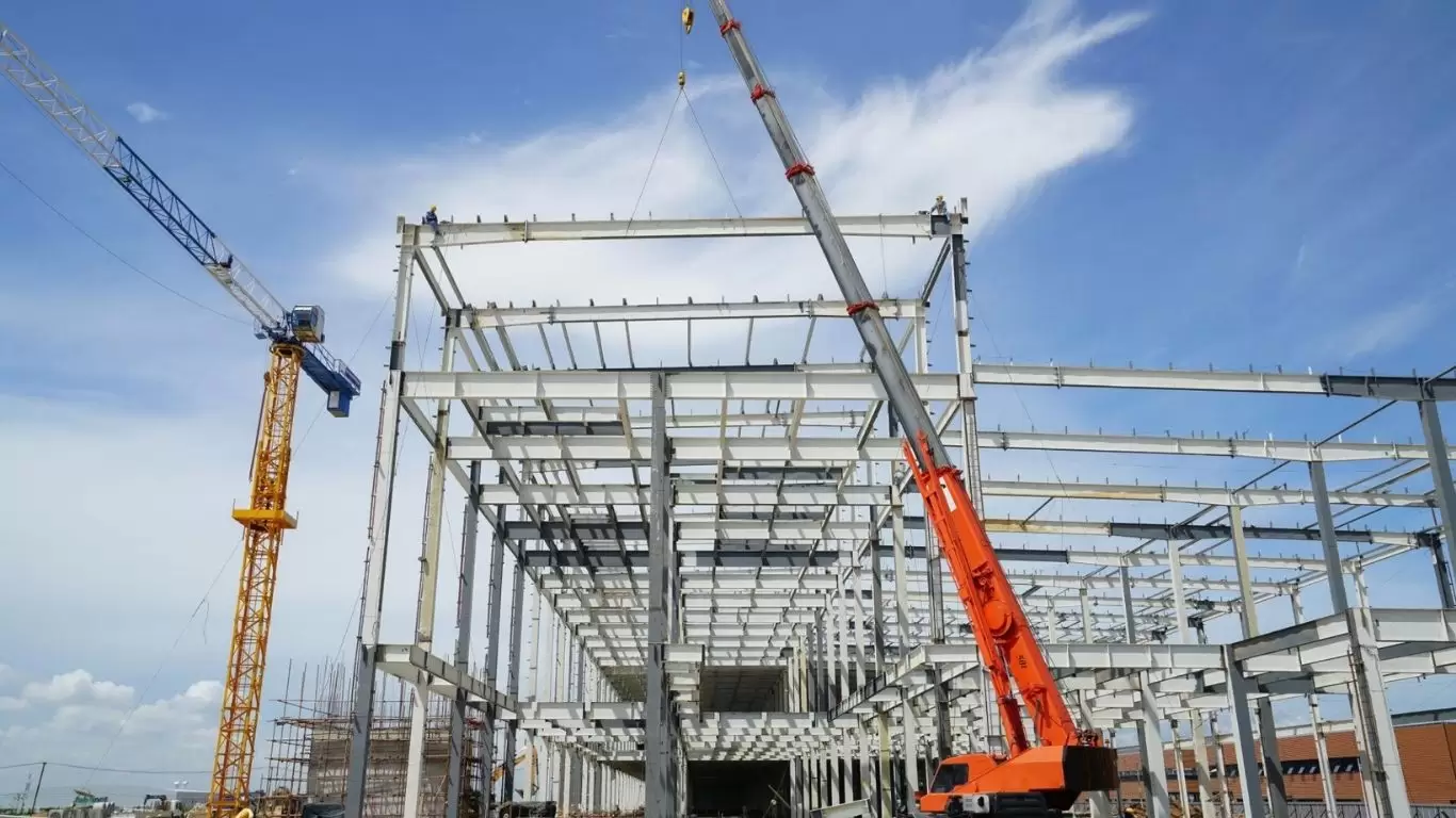
7. Steel Truss Erection: Sequencing, Temporary Stability, and Safety
Erection engineering for steel trusses is one of the most technically demanding and risk-intensive phases of industrial construction. This section addresses the engineering considerations that determine whether truss erection proceeds safely and on schedule.
Why Truss Erection Is Different from Beam Erection
A steel beam is a structurally complete element the moment it is lifted and placed on its supports — it can carry load in all planes as soon as the connection bolts are installed. A truss is different: a single truss without lateral bracing to adjacent trusses is unstable out-of-plane. The compression chord can buckle laterally, and the truss as a whole can tilt and topple unless adequate temporary bracing is in place.
The erection sequence must be planned so that, at every stage of the construction, each erected truss is adequately braced. The general sequence for a multi-bay truss roof:
- Step 1: Erect first truss panel — install first truss bay in its supports and immediately attach temporary erection bracing to the previous structural bay or to temporary props.
- Step 2: Erect second truss — once the first truss is braced, lift and place the second truss. Connect permanent plan bracing (at roof level between top chords) and permanent bottom chord bracing between trusses 1 and 2.
- Step 3: Install purlins between trusses 1 and 2 — purlins provide continuous lateral restraint to the top chord and significantly increase out-of-plane stability.
- Step 4: Remove temporary bracing — only after purlins are fully bolted and permanent bracing is installed and tensioned.
- Step 5: Proceed to subsequent bays — repeat sequence, checking that partial-structure stability is maintained at all stages.
Crane Selection and Rigging
Pre-assembled large-span trusses may weigh 10–50 tonnes per truss. Crane selection is based on:
- Lift weight: Truss weight plus rigging equipment weight plus dynamic factor (typically ×1.15 for crane sizing).
- Lift radius: Distance from crane centre to truss centroid at full reach. Crane capacity decreases rapidly with radius; maximum capacity is only available at minimum radius.
- Hook height: The crane hook must be able to lift the truss to the underside elevation plus sufficient clearance for slings and spreader beam.
- Spreader beam requirement: Long trusses (> 18 m) must be lifted with a spreader beam to distribute the crane hook load across multiple lift points, preventing top chord overstress due to vertical sling forces.
For very large trusses or confined sites, tandem lifts (two cranes simultaneously lifting a single truss) are used. Tandem lifts require a detailed lift plan, load sharing analysis, and coordination of crane operators under a qualified rigger’s supervision.
Temporary Bracing Design
Temporary bracing must be designed — not estimated — by a structural engineer. The bracing must carry the out-of-plane forces that the incomplete structure generates, including wind load on the partial structure and destabilising forces from imperfect truss plumb alignment. AISC Design Guide 6 (Erection Bracing of Low-Rise Structural Steel Buildings) and similar guidelines provide the engineering framework for temporary bracing design. Temporary bracing is typically: wire rope sway bracing attached to previously erected steelwork; prop legs or kicker braces to the ground; or temporary plan bracing members clamped to chords.
8. Industrial Applications: Steel Trusses by Building Sector
The following sector-by-sector overview maps truss types, span requirements, and critical design drivers to the B2B project categories most relevant to industrial developers, EPC contractors, and owner-operators.
Manufacturing Plants and Industrial Facilities
Manufacturing plants present the most demanding truss design conditions due to overhead travelling cranes (OHC). Heavy crane runway beams are supported by crane columns, which in turn transfer loads to the primary structural frame. Where headroom constraints require crane runway support directly from the roof truss bottom chord (suspension crane or underslung crane configuration), the truss is specifically designed as a crane-supporting transfer truss with panel point loads replacing the standard uniform distribution assumption. Fatigue design per AISC Design Guide 7 or EN 1993-1-9 is mandatory.
More about the tallest shipyard in Batangas, the Philippines (as of 2018) with a height of 33.5m that is designed, fabricated, and installed by Pebsteel.
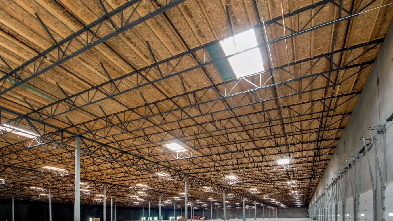
Warehouse and Logistics Facilities
Modern high-bay logistics and distribution centres (DCs) require column-free floor areas of 50,000–200,000 m² with clear internal heights of 12–18 m for automated racking systems. The roofing structure is typically a Pratt or Warren truss spanning 25–50 m between column lines at 6–9 m bay spacing. Key design drivers: minimum dead load (to reduce column and foundation loads on large floor plates); deflection limits (L/300 to L/400 for roof beam-to-column alignment); and provision for rooftop PV arrays (additional superimposed dead load of 0.3–0.5 kPa).
Aircraft Hangars
Aircraft hangars require the largest clear spans in industrial construction: 60 m to 200+ m for wide-body jet hangars. The structural system is either a long-span space frame (for spans > 80 m) or a deep Warren or Pratt truss at 1:8 to 1:10 d/L ratio (for spans 40–80 m). The critical design case is often net uplift from wind on the large-area flat roof, reversing the dominant force pattern from compression-top-chord to tension-top-chord and requiring uplift-specific connection detailing. Hangar door framing — typically a heavy-transfer truss spanning the full door opening width — is a specialist structure within the hangar that requires dedicated structural design.
Commercial Structures
- Shopping malls
- Exhibition halls
- Hotels & Resorts
More about Manila Bay Resorts And Its Impressive Curved Steel Trusses Corridor By Pebsteel
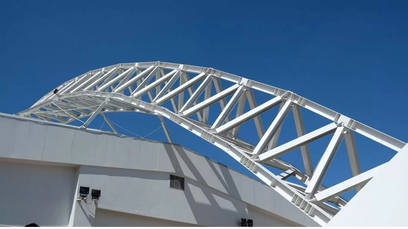
Stadium Canopies and Sports Facilities
Stadium roof canopies span 30–100 m from the facade ring beam to the back of the stand. Cantilever truss configurations with inclined back ties (forming a propped cantilever truss geometry) are common. Dynamic analysis for wind and for crowd-induced resonance is essential; the natural frequency of the canopy truss must avoid resonance with wind buffeting frequencies (typically < 1 Hz) and with rhythmic crowd activity frequencies (1.5–3 Hz for jumping and swaying). Connection fatigue under wind-induced oscillations must be checked per EN 1993-1-9 fatigue detail categories.
Transmission Towers, Substations, and Utility Structures
Transmission line towers are perhaps the most optimised truss structures in existence — every member is a tension or compression bar with no bending, and decades of design iteration have produced highly efficient angle-section Pratt lattice towers that carry conductors across spans of 300–600 m between towers while resisting extreme wind and ice loads. Substation structures (busbars, transformer gantries, switch frames) use similar angle-lattice or RHS truss construction. Design is governed by national transmission standards (IEEE, IEC 60826, AS 7000) rather than building codes.
9. Material Standards for Steel Trusses: International Code Comparison
Steel truss members are fabricated from structural steel plates, rolled sections, and hollow sections to material standards that govern yield strength, tensile strength, ductility, toughness, and weldability. The governing standard depends on the project jurisdiction and specification.
|
Standard |
Grade | Fy (MPa) | Primary Market |
Typical Truss Application |
| ASTM A36 | A36 | 250 | North America | Secondary members, gusset plates |
| ASTM A572 | Grade 50 | 345 | North America | Chord plates, web members in built-up trusses |
| ASTM A500 | Grade C | 317 | North America | Cold-formed HSS truss members |
| EN 10025-2 | S275 / S355 | 275 / 355 | Europe, ME, Africa | S355J2 standard for chord & web members |
| EN 10219/10210 | S355J2H | 355 | Europe, ME, Africa | Cold-formed or hot-finished HSS truss members |
| AS/NZS 3678 | Grade 350 | 360 (t≤17mm) | Australia, Pacific | Plate-fabricated chord sections |
| AS/NZS 1163 | C350L0 | 350 | Australia, Pacific | Cold-formed RHS/CHS truss members |
| IS 2062 | E250/E350 | 250 / 350 | India, South Asia | All truss member types |
For seismic applications, material ductility requirements are more stringent. AISC 341-22 (Seismic Provisions) requires Fy ≤ 380 MPa and Fy/Fu ≤ 0.85 for members in Special Concentrically Braced Frames (SCBF), which share design principles with seismically detailed trusses. EN 1998-1 requires Class 1 sections (capable of developing full plastic rotation) for ductile truss members in dissipative seismic systems.
10. Corrosion Protection and Fire Protection for Steel Trusses
Coating Systems by Exposure Category
Surface preparation and coating specification follows the same principles as for steel beams, referenced to ISO 12944-2 corrosivity categories. However, trusses present an additional complexity: the large number of member connections and node details creates many crevice zones (back-to-back angles, bolted connections, gusset plate interfaces) where moisture can penetrate and initiate crevice corrosion. Design measures include: seal welding of all crevice zones with continuous fillet welds; specifying galvanizing for truss members in C4 (industrial/urban) and C5/CX (marine/offshore) environments; using closed hollow sections (RHS/CHS) to eliminate internal corrosion risk in the web members.
Hot-Dip Galvanizing for Trusses
Hot-dip galvanizing (HDG) per EN ISO 1461 or ASTM A123 is the preferred long-term corrosion protection for steel trusses in exposed or difficult-to-maintain environments. For trusses, galvanizing requires all hollow section members to have vent holes at each end to allow zinc flow through the interior and to prevent air lock and explosion during immersion. Vent hole size and position is specified in BS EN ISO 14713 and ASTM A385. Maximum truss dimension for galvanizing is limited by the kettle size — typically 13–15 m in the longest dimension for standard kettles, requiring trusses to be galvanized in sections and spliced after dipping.
Fire Protection of Exposed Trusses
Open-web trusses present a significantly greater surface area per unit mass than equivalent solid beams, which means they lose heat to fire faster and the steel temperature rises more rapidly. Intumescent coatings are the most practical fire protection method for exposed architectural trusses (Section Factors Hp/A up to 400 m⁻¹ for light angle web members). Required intumescent DFT for 60-minute fire resistance can reach 3–6 mm for light-section web members, which must be accounted for in fabrication sequencing and aesthetic finish specifications. For industrial buildings with automatic sprinkler protection, performance-based fire engineering (using computer fire models such as FDS) can often demonstrate that applied fire protection is not required for roof trusses above the sprinkler design height.
11. B2B Procurement Considerations: Specification, Quality, and Lead Time
Complete Truss Specification Checklist
A complete truss procurement package for large-scale industrial projects should specify:
- Truss type, span, and panel configuration (with preliminary geometry drawing or outline specification)
- Design loads: dead, live, wind, snow, crane (if applicable), with applicable code reference
- Material grade and standard (ASTM / EN / AS / IS) with Charpy impact test temperature if applicable
- Execution Class (EN 1090-2 EXC2 or EXC3) or AISC Category of Standard Practice, with NDT requirements
- Fabrication tolerances: reference AISC CoSP Section 7 or EN 1090-2 Table D.1
- Camber requirement: magnitude and measurement method
- Surface preparation: Sa 2.5 per ISO 8501-1 or SSPC SP-10
- Primer specification: product, DFT, application method
- Fire protection: type, FRR required, applicable test standard (EN 13381-8, ASTM E119)
- Transport and erection: maximum pre-assembled section weight and dimensions; erection bolts and hardware
- Mill Test Reports (MTRs) and Certificate of Conformance for all structural steel
- Third-party inspection (TPI) hold/witness points
Lead Time Planning
|
Phase |
Standard Project (< 50 t trusses) |
Complex/Large Project (> 200 t trusses) |
| Engineering and design | 4–6 weeks | 8–12 weeks |
| Material procurement (plates, sections) | 4–6 weeks | 6–10 weeks |
| Fabrication (concurrent with material) | 6–10 weeks | 12–20 weeks |
| Surface treatment and inspection | 2–3 weeks | 3–5 weeks |
| Ocean freight (Asia to Middle East) | 3–4 weeks | 3–5 weeks (multiple vessels) |
| Total minimum programme | 16–22 weeks | 28–40 weeks |
12. Why Choose Pebsteel for Steel Trusses?
Our word, our bond.
Once a project is initiated, our relationship with the customers becomes permanent. Once the building is erected, we provide indefinite maintenance and customer service.
We serve customers ranging from developers and contractors to direct investors in all industries.
We use our own multi-functional industry-standard products to produce buildings with eye-catching quality.
Architectural flexibility
Accessories such as trims, gutters and fascias can be customized to enhance the aesthetics. We have an unlimited color palette to choose from, in addition to our standard colors. Combining steel with other materials such as brickwork or glass gives unlimited scope in architectural design.
Functional versatility
There is no one-size-fits-all with pre-engineered steel buildings. The buildings´structures can be customized to reach their maximum potential. Pebsteel can handle huge unobstructed indoor spaces, with up to 180m between columns and large bay spacing up to 15m.
Environmental friendliness
We proudly meet the sustainability criteria described by LEED® with our certified products and building solutions. We also help our customers obtain their own certifications in environmental management and sustainability.
Our Key Strengths
- Design + fabrication integration
- Proven international projects
- Cost-efficient solutions
13. Conclusion
Steel trusses are a highly efficient structural solution that combines engineering precision with economic performance. Their ability to span large distances, optimize material usage, and integrate with prefabrication systems makes them indispensable in modern construction.
For developers and engineers aiming to maximize efficiency, reduce cost, and ensure long-term performance, steel trusses remain the preferred structural system.
👉 Partnering with an experienced provider like Pebsteel ensures optimal design, quality, and project success.
Disclamer: The content provided in this article is for reference purposes only. For further details or clarification based on your needs, please contact Pebsteel directly.