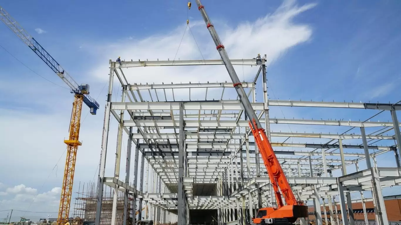
A steel framework is the load-bearing skeleton of any steel-framed building — the engineered assembly of columns, beams, bracing, and connections that transfers every applied force safely to the foundation. From a single-storey distribution warehouse to a multi-storey manufacturing complex, the steel framework defines the building’s structural integrity, spans its usable space, determines its seismic and wind resistance, and governs the speed and cost of its construction.
For B2B decision-makers — project developers, EPC contractors, procurement managers, and structural engineers — understanding steel framework systems at a technical level is the foundation of sound investment decisions. Yet most publicly available resources on steel frameworks limit their coverage to naming frame types and listing generic advantages. They omit the technical depth that actually drives specification decisions: lateral resistance system selection, composite construction, seismic design category requirements, total cost of ownership versus concrete, connection classification, column baseplate engineering, and procurement quality assurance.
This guide addresses all of those gaps. It is written by PEB Steel Buildings, one of Asia’s most experienced integrated steel framework manufacturers, specifically for B2B readers who need engineering-level clarity to make confident specification and sourcing decisions.
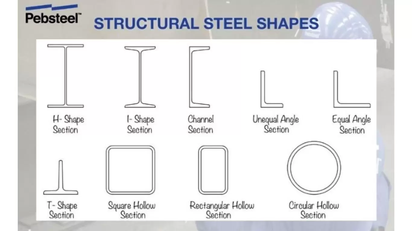
1. What Is a Steel Framework? Definition and Structural Anatomy
A steel framework — also called a structural steel frame or steel skeletal structure — is a three-dimensional assembly of primary and secondary structural steel members designed to carry all gravity loads (dead, live, snow, equipment) and lateral loads (wind, seismic) acting on a building and to deliver those loads to the ground through the foundation system.
The framework is composed of four functional layers:
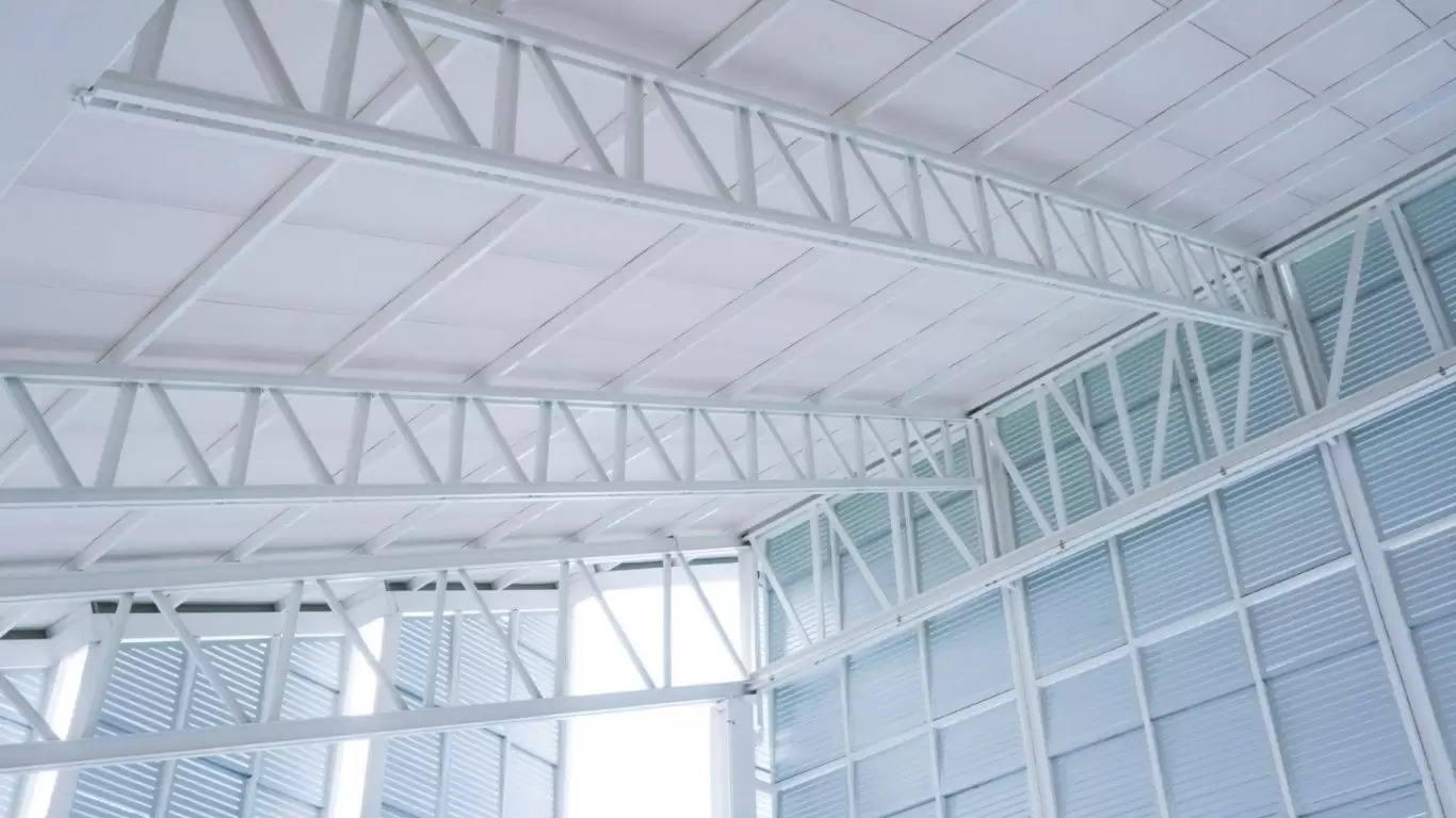
- Primary structural members: Columns (vertical, predominantly compression) and primary beams or rafters (horizontal or inclined, predominantly bending). These members define the structural bay grid and carry the majority of the total load.
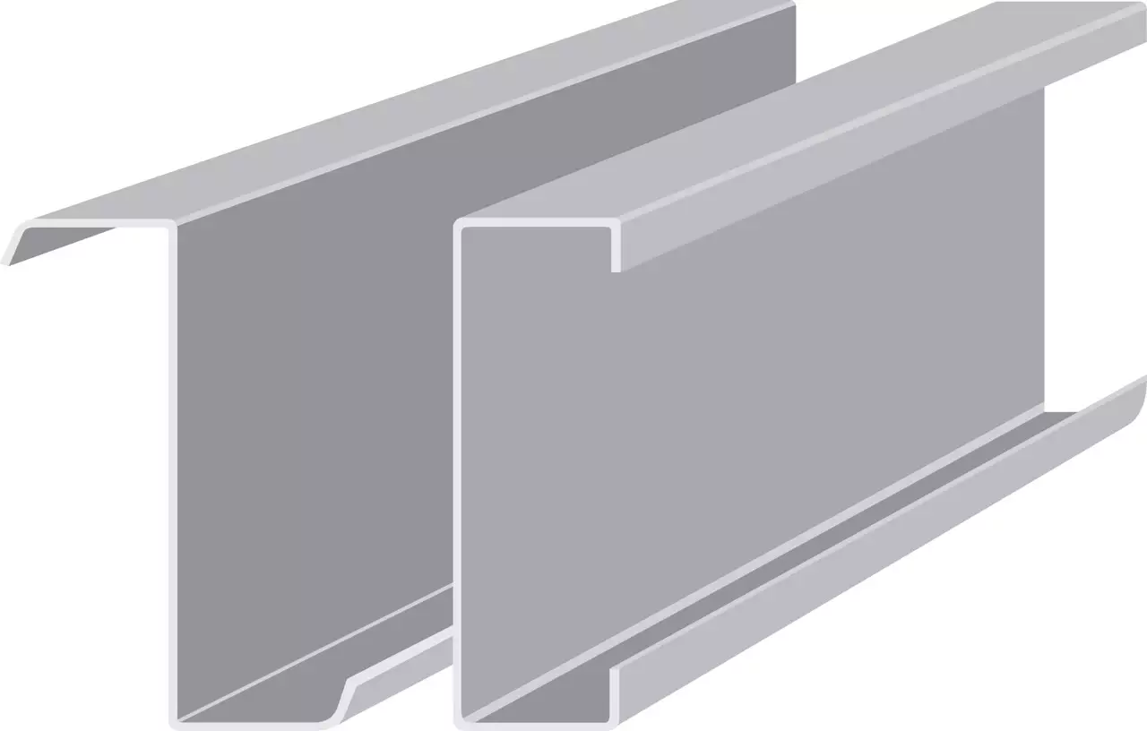
- Secondary structural members: Purlins (roof), girts (walls), floor beams, and mezzanine beams that span between primary members and transfer applied loads to them.
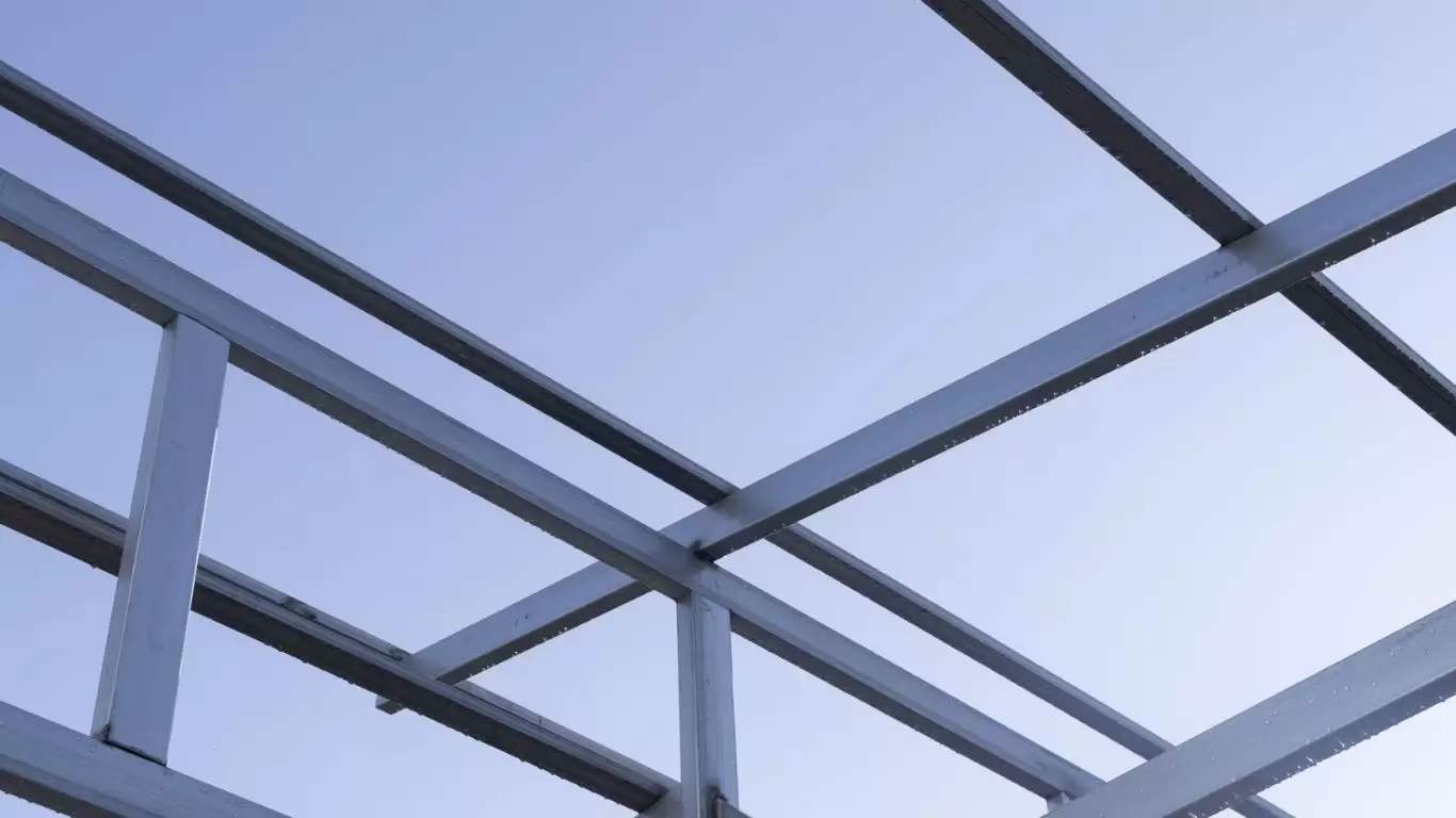
- Lateral load-resisting system: Bracing (concentric, eccentric, or knee-brace), moment-resisting frames, or shear walls — the elements that resist horizontal wind and seismic forces and prevent the framework from racking or overturning.
- Connections and base: Beam-to-column connections, column splices, and column base plates with anchor bolts — the interface elements that transfer forces between members and between the framework and the foundation.
Together, these four layers form a complete, engineered system. The performance of the whole depends on the quality of every component and every connection within it.
2. Types of Steel Framework Systems
Steel frameworks are classified by the structural logic used to carry gravity and lateral loads. Selecting the right system for a specific building use and site condition is one of the most consequential early-stage engineering decisions.
2.1 Braced Steel Framework (Simple / Pin-Jointed Frame)
In a braced steel framework, beams are connected to columns with nominally pinned connections that transfer shear but not bending moment. The frame resists gravity loads through beam bending and column compression. Lateral load resistance (wind, seismic) is handled entirely by a separate bracing system — typically steel X-braces, V-braces, or K-braces in designated bays — or by a concrete core.
This system is structurally efficient because beam-to-column connections are simple and inexpensive (shear tabs, double angles), and the bracing elements are sized independently for lateral load only. Braced frames are the most cost-competitive structural solution for multi-storey commercial, industrial, and logistics buildings when the bracing can be located in non-intrusive bays (stair cores, service risers, external walls). They are the dominant framework choice for buildings up to approximately 20 storeys.
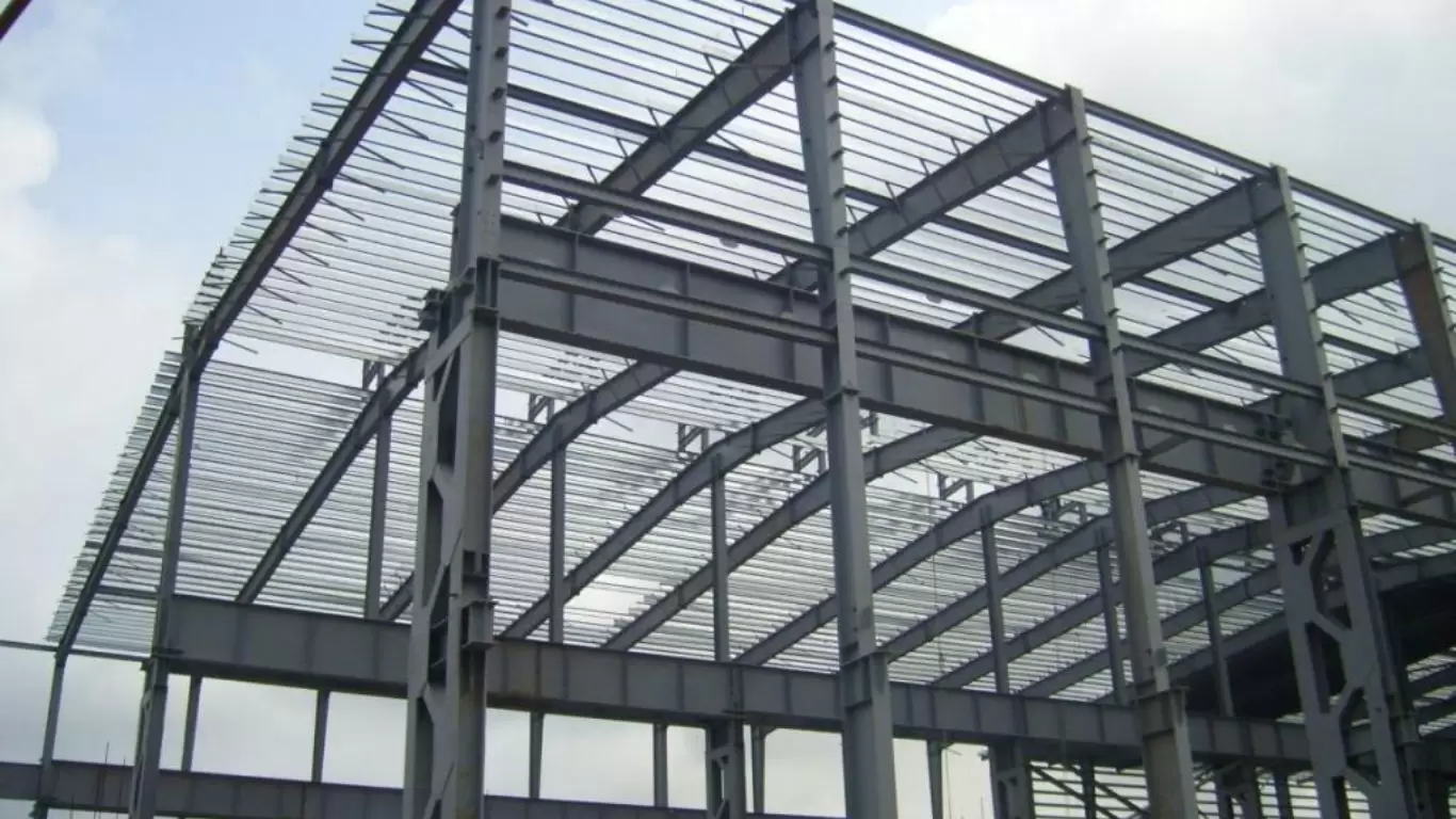
2.2 Moment-Resisting Steel Framework (Rigid Frame)
In a moment-resisting framework, beam-to-column connections are designed to be rigid — capable of transferring both shear and bending moment. The connections provide rotational continuity, allowing the frame itself to resist lateral loads through frame action without diagonal bracing.
Moment frames are preferred when bracing locations are architecturally or functionally constrained — for example, in fully glazed building facades, open-plan office interiors, or large-span industrial buildings where cross-bracing would obstruct clear passage. The trade-off is more complex, heavier connections (extended end plates, welded moment connections) and higher fabrication cost per connection compared to simple pinned connections. In seismic design, Special Moment Frames (SMF) per AISC 341 provide high ductility and energy dissipation, making them the system of choice for high seismic risk zones.
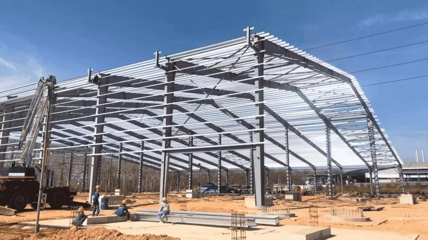
2.3 Portal Frame (Pre-Engineered Framework)
A portal frame is a single-bay, single-storey moment-resisting frame formed by two columns rigidly connected to an inclined or horizontal rafter at the eave. The rafter and column act as a single integrated structural unit, with the moment continuity at the knee joint (eave connection) providing both gravity and lateral load resistance without any separate bracing within the clear-span interior.
Portal frames are the structural basis of every Pre-Engineered Building (PEB) system and are the dominant framework for industrial warehouses, logistics facilities, manufacturing plants, cold storage buildings, and commercial structures worldwide. In PEB systems, the columns and rafters are fabricated as tapered built-up I-sections, with depth varying along the member length to match the bending moment diagram — delivering material efficiency of 15–30% compared to equivalent constant-depth rolled sections.
2.4 Long-Span Steel Framework
For steel structures where clear-span requirements exceed the practical range of standard portal frames (> 90 m) or where column-free floors are required at multiple levels, long-span frameworks using trusses, space frames, or castellated/cellular beams provide the structural solution. These systems trade higher fabrication cost for the operational value of unrestricted interior space and the ability to route services through the structural depth.
2.5 Multi-Storey Steel Framework
Multi-storey steel frameworks combine a primary gravity frame (columns and floor beams) with a lateral resistance system (braced cores, moment frames, or combined) and a floor deck system (composite steel deck with concrete topping, or precast planks on steel beams). Multi-storey steel frameworks are standard for commercial office buildings, data centres, car parks, and mixed-use developments. Connection standardisation and modular bay dimensions are critical for programme and cost efficiency in multi-storey steel.
| Framework System | Lateral Resistance | Typical Storeys | Best Suited Application |
| Braced frame | Steel bracing / core | 1–20 | Offices, logistics, multi-storey commercial |
| Moment frame | Frame action | 1–30 | Open facades, seismic zones, SMF/IMF |
| Portal / PEB frame | Frame action (eave moment) | 1 | Warehouses, factories, logistics, cold storage |
| Long-span (truss/space frame) | Combined | 1 | Hangars, stadiums, large industrial |
| Multi-storey composite | Bracing + moment frame | 2–30+ | Data centres, offices, mixed-use |
3. Pre-Engineered (PEB) Framework vs Conventional Steel Framework: A Technical Comparison
The distinction between a Pre-Engineered Building (PEB) framework and a conventional steel framework is one of the most practically important differentiators in industrial steel construction.
| Dimension | PEB Framework | Conventional Steel Framework |
| Member design | Tapered built-up I-sections matched to bending moment diagram | Standard hot-rolled sections (W, H, S) — constant depth |
| Material efficiency | 15–30% less steel vs equivalent constant-depth frame | Baseline; excess material at low-moment zones |
| Design process | Proprietary optimisation software; design-build in single contract | Engineer-designed per project; separate design and supply contracts |
| Span capability | Up to 90 m+ clear span; standard 15–60 m | Up to ~30 m with rolled sections; longer with plate girders |
| Erection speed | Fast — all members pre-drilled, matched; bolt-up assembly | Moderate — more field welding and fit-up adjustment |
| Expandability | Standard end-wall frames designed for future bay additions | Expansion requires new design; may need structural upgrading |
| Cost model | Lower total installed cost for single-storey industrial (1,000–50,000 m²) | Competitive for multi-storey or highly customised geometry |
| Quality control | Factory QC on all members; single-source accountability | Multiple fabricators; interface risk between supply packages |
PEB Steel engineering note: For single-storey industrial buildings between 500 m² and 100,000 m² floor area, PEB portal frame frameworks consistently deliver the lowest total installed cost per square metre, shortest construction programme, and best expandability for future growth. For multi-storey or highly bespoke structures, conventional frameworks may be the appropriate choice.
4. Lateral Load Resistance: Selecting the Right System for Your Steel Framework
Every steel framework must resist lateral loads — wind pressure and suction, seismic inertia forces, and crane-induced horizontal thrust. The choice of lateral resistance system significantly affects structural cost, connection complexity, interior flexibility, and seismic performance. This selection criterion is missing from every competing guide reviewed.
4.1 Concentric Braced Frame (CBF)
Steel diagonal braces (typically circular hollow sections, angles, or flat bars in X, V, or inverted-V configuration) are the most cost-effective lateral resistance element for steel frameworks in low-to-moderate seismic zones. Bracing members carry lateral load in pure axial tension and compression, with nominally pinned connections at each end. This makes bracing simple to design, fabricate, and inspect.
The limitation: brace panels must be located in specific bays, potentially constraining door openings, vehicle access routes, or equipment clearances. Inverted-V (chevron) bracing allows a door or opening at the base of the brace panel. In seismic design, Ordinary (OCBF) and Special (SCBF) concentrically braced frames per AISC 341 provide increasing levels of ductility at increasing connection complexity and cost.
4.2 Moment-Resisting Frame (MRF)
Where bracing is architecturally or functionally incompatible, moment-resisting connections between beams and columns carry lateral loads through frame bending stiffness. MRFs provide full bay-width openings free of diagonal members — ideal for glazed facades, wide-door warehouse elevations, and open-plan office interiors. The engineering cost is heavier, more complex connections (extended end plates, welded moment connections with continuity plates) and a more flexible lateral response than an equivalent braced frame.
In seismic design, Special Moment Frames (SMF) and Intermediate Moment Frames (IMF) per AISC 341 / FEMA 350 define specific connection requirements and compactness criteria to ensure ductile plastic hinge formation in the beam away from the column face — protecting the connection itself from fracture.
4.3 Knee-Brace (Portal Knee) Hybrid
In single-storey industrial buildings, a knee brace — a diagonal member connecting the column to the rafter at a point below the eave — provides lateral stiffness without a full-height diagonal brace that would obstruct the building interior near the wall. Knee braces are a common and cost-effective lateral solution in PEB portal frame systems for tall eave heights where the portal frame alone is less efficient as a lateral element.
4.4 Matching Lateral System to Seismic Design Category
| Seismic Risk | ASCE 7 SDC | Permitted Systems (AISC 341) | Connection Requirement |
| Low | A / B | OCBF, OMF, portal frame | Standard bolted or welded; no special detailing |
| Moderate | C | SCBF, IMF, OCBF | IMF connections tested per AISC 358; SCBF compactness |
| High | D / E / F | SCBF, SMF, EBF | SMF/EBF: prequalified connections per AISC 358; RBS or bolted end plate |
5. Composite Steel Framework: Increasing Efficiency with Steel-Concrete Integration
Composite construction — where structural steel beams act compositely with a reinforced concrete slab through mechanical shear connectors (headed shear studs) — is the standard approach for multi-storey steel floor systems globally and one of the most significant content gaps in competing guides.
In a composite floor beam, the concrete slab contributes to the beam’s bending resistance as a compressive flange, increasing the effective section modulus by 30–50% compared to the bare steel section alone. This allows the engineer to specify a lighter steel section (or a wider span for the same section) while maintaining the same structural performance. The result is a floor system that uses less steel per square metre than a non-composite equivalent, reducing both material cost and self-weight — which in turn reduces column sizes, bracing demands, and foundation loads.
5.1 How Composite Action Works
Headed shear studs (typically 19 mm diameter × 100 mm long) are welded to the top flange of the steel beam through the steel deck. These studs mechanically lock the concrete slab to the steel beam, preventing relative slip between the two and forcing them to act as a single composite section. The degree of composite action (full or partial) is defined by the ratio of shear studs provided to the number required for full composite action. Partial composite ratios of 50–75% are common in practice, delivering most of the efficiency benefit at lower stud count and installation cost.
5.2 Steel Deck and Composite Slab
The steel deck (profiled cold-formed steel sheeting, typically 0.75–1.0 mm thick, in depths of 51, 76, or 80 mm) serves as both permanent formwork during concrete placement and as positive moment reinforcement in the completed composite slab. The deck profile geometry affects the effective composite beam properties because the ribs of the deck that run perpendicular to the beam reduce the shear stud strength (stud strength reduction factor per AISC 360 Chapter I or EN 1994-1-1).
Total slab thickness (deck soffit to slab top) is typically 130–160 mm for commercial office and industrial mezzanine floors, giving a finished composite floor weight of approximately 2.5–3.5 kN/m² — significantly lighter than a 200 mm reinforced concrete flat slab (approximately 4.8 kN/m²).
6. Column Baseplate and Anchor Bolt Design: The Critical Foundation Interface
The column baseplate is the structural interface between the steel framework and the concrete foundation — one of the most technically critical details in any steel building, yet entirely absent from competing guides. A poorly designed baseplate or incorrectly installed anchor bolt group has caused costly project delays, field rework, and in rare cases, structural failure during erection.
6.1 Baseplate Functions
- Axial load transfer: Distributes the concentrated column axial load (compression or tension under uplift) over a sufficient bearing area on the concrete foundation to keep bearing stress within the concrete’s design capacity (typically φ0.85f’c per ACI 318 or fRd per EN 1992).
- Shear transfer: Transfers horizontal shear (wind, seismic, crane horizontal thrust) from column base to foundation via friction between baseplate and grout, shear keys welded to the base plate underside, or shear loaded on anchor bolt shank.
- Moment transfer: For fixed-base columns (portal frames, moment frames, cantilever columns), the baseplate must transfer the column base moment. This is achieved through the lever arm between the compression bearing zone and the tension anchor bolt group, creating a force couple that resists the applied moment.
6.2 Design Parameters
Baseplate thickness is governed by the cantilever bending of the plate from the column profile edge to the plate edge. For heavily loaded or moment-base columns, plates of 25–60 mm thickness are common. The required plate area is:
A_req = P_u / (φ × 0.85 × f’c) [Bearing area for column axial load, AISC Design Guide 1]
Anchor bolts are designed for tension under moment and uplift, shear under lateral loads, and combined tension-shear under combined loading. Standard anchor bolt grades are ASTM F1554 Grade 36, 55, or 105 (for high-strength applications). Anchor bolt projection above the baseplate is typically 75–150 mm to allow for shim plates (used to level the base plate during erection) and grouting. All anchor bolt locations and projections must be specified in the structural drawings and confirmed with the civil/foundation engineer before concrete placement — post-installation corrections are extremely costly.
7. Total Cost of Ownership: Steel Framework vs Reinforced Concrete Framework
The most persistent misconception in industrial construction procurement is that reinforced concrete (RC) frameworks are cheaper than steel frameworks. This comparison is almost always made on material cost alone — ignoring construction programme cost, foundation cost, lifecycle cost, and asset value. When total cost of ownership (TCO) is properly calculated, steel frameworks frequently outperform RC on a lifecycle basis, particularly for industrial buildings.
| Cost Category | Steel Framework | RC Framework |
| Structural material cost | Moderate–high per tonne; lower total tonnes | Lower unit material cost; higher total volume |
| Foundation cost | Lower — steel self-weight is 60–75% lighter | Higher — RC dead load significantly increases footing/pile sizes |
| Construction time | 30–50% faster on site; factory fabrication off critical path | Longer — formwork, cure cycles, sequential pour programme |
| Programme cost saving | Earlier revenue from tenant / operations by 2–6 months | Later revenue start; higher project finance carrying cost |
| Future adaptability | High — openings, extensions, additional floors relatively simple | Low — structural modifications require specialist engineering and demolition |
| End-of-life value | Steel scrap value recoverable; 90%+ recyclable | Demolition cost; concrete waste to landfill or crush |
| Maintenance (corrosion) | Periodic coating inspection / touch-up; HDG for long-term | Crack repair, carbonation protection in aggressive environments |
| Typical break-even (TCO) | Steel generally equals or outperforms RC at 15–20-year NPV for industrial | RC may have lower initial cost for certain RC-intensive markets |
The programme cost saving deserves particular attention. For a large logistics facility (50,000 m² floor area) with monthly rent of USD 400,000, two months earlier completion from steel construction is worth USD 800,000 — frequently exceeding any material cost premium of steel over concrete. This calculation is routinely omitted from construction cost comparisons but is one of the primary reasons institutional developers and logistics REITs globally specify steel frameworks for industrial assets.
8. International Standards for Steel Framework Design
Steel framework design is governed by national and regional codes that specify load combinations, member design methods, connection requirements, and material standards. For B2B buyers procuring frameworks across multiple geographies, understanding which code governs is essential for ensuring compliance and audit trail.
| Standard | Market | Structural Design | Material Standard |
| AISC 360 + ASCE 7 | USA, Americas, international | LRFD or ASD; AISC 341 for seismic | ASTM A992, A572, A500, A36 |
| EN 1993 + EN 1990/1991 | Europe, Middle East, Africa | Eurocode 3; EN 1998 for seismic | EN 10025 S275/S355; EN 10219/10210 HSS |
| AS 4100 + AS/NZS 1170 | Australia, NZ, Pacific | LRFD-based; AS 1170.4 seismic | AS/NZS 3678 Grade 300/350 |
| IS 800 + IS 875 | India, South Asia | Limit state design | IS 2062 E250/E350 |
| GB 50017 | China | Chinese limit state | GB/T 1591 Q345/Q355 |
PEB Steel designs to AISC/ASCE, EN 1993/1990, AS 4100, and IS 800 — covering the full range of global markets. Every project is delivered with full design documentation, material certificates, and drawing packages referencing the applicable code.
9. Steel Framework Applications by Industrial Sector
9.1 Logistics and Distribution Centres
The global logistics sector is the single largest consumer of industrial steel frameworks. Distribution centres (DCs) and fulfilment centres require column-free floor areas of 10,000–200,000 m², clear internal heights of 10–18 m for automated racking, level floors (FM2 flatness standard or better), and robust eave-level connections for dock levellers and dock shelters. PEB portal frame frameworks with 30–60 m clear spans and 9 m bay spacing are the standard structural system for this sector. Expandability — the ability to add bays to the end wall without structural compromise — is a mandatory design consideration.
9.2 Manufacturing and Industrial Plants
Manufacturing facilities introduce structural demands beyond those of simple logistics buildings: overhead travelling cranes (OHC) from 1 tonne to 200+ tonnes capacity; mezzanine structures carrying process equipment loads of 5–20 kN/m²; explosion relief panels requiring vented cladding details; vibration-sensitive equipment requiring specific floor frequency criteria; and chemical or wash-down environments demanding enhanced corrosion protection. Steel frameworks for manufacturing plants are almost always designed as crane-building portal frames with dedicated crane columns, crane runway beams, and plan bracing systems designed for the full dynamic crane load combination.
9.3 Cold Storage and Refrigerated Logistics
Cold storage frameworks must accommodate the thermal contraction of the building envelope, prevent thermal bridging through the structural steel (which can cause condensation and ice formation at column base connections), and support the substantial dead load of insulated panel systems. PEB frameworks with thermally broken base conditions, oversized purlins and girts for panel support, and detailed vapour barrier continuity at all structural penetrations are the engineered response to these requirements.
9.4 Commercial and Mixed-Use Buildings
Multi-storey steel frameworks for office, retail, and mixed-use developments combine composite floor beams (for material efficiency and services integration), braced or moment-frame lateral systems (depending on seismic zone and facade design), and architectural cladding systems hung from the primary frame. Floor-to-floor height optimisation — using shallow floor systems (Slimdek, Deltabeam, or similar) to minimise structural depth while maintaining services clearance — is a critical value engineering exercise in commercial steel frameworks.
9.5 Data Centres
Data centre structural frameworks are characterised by extremely high floor loads (battery rooms: 10–20 kN/m²; UPS rooms: 8–15 kN/m²; server halls: 5–10 kN/m²), stringent vibration criteria (floor frequency > 10 Hz to protect sensitive equipment), tight erection tolerances (± 2 mm for raised floor grid alignment), and requirements for 100% backup power systems including heavy diesel generator sets on the roof or ground floor. Steel frameworks — particularly multi-storey composite frames — are the preferred structural system for data centre construction due to speed, the ability to carry heavy point loads with efficient transfer structures, and the availability of certified recycled-content steel for Scope 3 carbon reporting.
10. B2B Procurement Guide: Specifying and Sourcing a Steel Framework Package
For large-scale industrial projects, the procurement of a steel framework involves multiple technical and commercial decisions that must be made in the correct sequence. The following checklist addresses the key specification and qualification criteria that experienced procurement teams apply.
10.1 Technical Specification Checklist
- Structural system: Confirm framework type (portal frame, braced frame, moment frame, composite multi-storey) and span/bay dimensions.
- Governing design code: Specify AISC/ASCE, EN, AS, or IS — with applicable edition year and any local national annexes.
- Design loads: Dead load, live load (occupancy/equipment), wind speed and exposure category, seismic design category or PGA value, crane capacity and duty class (if applicable).
- Material grade: ASTM grade (A992, A572 Gr50, A500C) or EN grade (S355J2, S355J2H for HSS) — with Charpy impact temperature if required for cold-climate projects.
- Fabrication execution class: EN 1090-2 EXC2 (standard industrial) or EXC3 (seismic/fatigue-critical) — with corresponding NDT requirements.
- Surface preparation and coating: Sa 2.5 blast + zinc-rich primer (specify DFT) as minimum; HDG for corrosive environments; intumescent topcoat if fire resistance required.
- Connection hardware: Specify bolt grade (ASTM A325/A490 or Grade 8.8/10.9 per EN 14399), pretension method (snug-tight, turn-of-nut, or DTI washer), and inspection protocol.
- Dimensional tolerances: Reference AISC Code of Standard Practice Section 7 or EN 1090-2 Table D.1.
- Material traceability: Mill Test Reports (MTRs/CMTRs) required for all structural steel members with heat number traceability to final member.
- Erection hardware: Confirm whether erection anchor bolts, shim plates, and grouting are included in the framework supply scope.
10.2 Supplier Qualification Criteria
- Certifications: ISO 9001 Quality Management; EN 1090 CE Marking (EXC2/EXC3 as applicable); AISC Certification (Category STD, AISC Major or AISC Advanced for complex projects).
- Engineering capability: In-house structural design team with code-specific experience; ability to produce Approval for Construction (AFC) drawings and structural calculations.
- Welding certification: Certified Welding Inspector (CWI per AWS) or European Welding Engineer (EWE per EN ISO 14731) on staff; WPS and PQR to AWS D1.1 or EN ISO 15614.
- Track record: Project references in the same building type and similar scale; willingness to provide contact references from past clients.
- Integrated supply capability: Ability to supply primary steel, secondary steel (purlins, girts), roofing, cladding, and accessories from a single source — reducing interface risk.
10.3 Typical Lead Time Schedule
| Activity | Standard PEB Package | Conventional / Complex Frame |
| Structural engineering & AFC drawings | 4–6 weeks | 8–16 weeks |
| Material procurement | 3–5 weeks (concurrent) | 6–10 weeks |
| Fabrication (primary + secondary) | 6–10 weeks | 12–24 weeks |
| Surface treatment and QC inspection | 2–3 weeks | 3–5 weeks |
| Freight (Asia to Middle East / Africa) | 3–5 weeks | 4–6 weeks |
| Total programme to site delivery | 16–22 weeks | 28–40 weeks |
Why PEB Steel for Your Steel Framework Project
PEB Steel Buildings Co., Ltd. is one of Asia’s most experienced and largest integrated steel framework manufacturers, with manufacturing facilities in Vietnam and completed projects across 50+ countries in Southeast Asia, South Asia, the Middle East, Africa, and the Pacific. Our design-build model — from structural analysis and connection design through factory fabrication, surface treatment, and delivery — gives project owners and contractors a single, accountable partner for their complete steel framework package.
- In-house engineering: Full structural analysis (STAAD.Pro, SAP2000, Robot Structural Analysis) and member, connection, and foundation interface design to AISC, EN, AS, and IS codes. Seismic detailing, crane building design, and composite structure design are all handled within our engineering team.
- Integrated manufacturing: CNC plate cutting, automated SAW welding of primary members, cold-roll forming of purlins and girts, shot blast to Sa 2.5, multi-layer coating — all within our ISO 9001-certified facilities.
- Framework types delivered: PEB portal frames (clear span and multi-span), braced multi-storey frames, moment-resisting frames, long-span truss systems, crane buildings, cold storage structures, mezzanine structures, and modular building systems.
- Material sourcing: Structural plates from certified mills (POSCO, Nippon Steel, Baosteel, Tata Steel) with full CMTR traceability. Available in ASTM, EN, AS, IS, and JIS grades.
- Quality assurance: Full ITP available; third-party inspection (Bureau Veritas, SGS, Intertek) welcomed at all fabrication hold points; NDT (VT, MT, UT) as standard on primary weld groups.
- Project references: Warehouses and DCs (10,000–200,000 m²), manufacturing plants with 50t+ cranes, aircraft hangars, cold storage facilities, commercial buildings, data centres — across 50+ countries.
Contact PEB Steel directly to request a technical consultation, preliminary structural design, and budget estimate for your steel framework project.
Conclusion
A steel framework is far more than a commodity construction input — it is the structural intelligence of your building, encoding the engineering decisions that determine how safely, efficiently, and economically your facility will stand and serve its purpose for decades. Getting the framework system right — the correct lateral resistance strategy, the right composite floor approach for multi-storey applications, the appropriately designed column baseplates, the correctly specified material grade and execution class — is the foundation of a successful industrial project.
The 10 content gaps this guide addresses — PEB vs conventional framework comparison, lateral system selection and seismic matching, composite construction, column baseplate design, TCO versus concrete, international code comparison, and a complete B2B procurement specification checklist — represent the technical information that genuinely drives specification and procurement decisions in industrial construction. They are the topics where an experienced PEB manufacturer adds value beyond what a generic guide can provide.
PEB Steel is equipped to support your project from the earliest feasibility stage through to erected, inspected, and certified steel framework delivery — in any geography, to any applicable structural standard, at the schedule and quality level that industrial-scale construction demands.
Frequently Asked Questions
What is the difference between a braced steel framework and a moment-resisting framework?
In a braced framework, beam-to-column connections are pinned (shear only) and lateral loads are resisted by dedicated diagonal bracing members. In a moment-resisting framework, the connections are rigid, capable of transferring bending moment, allowing the frame itself to resist lateral loads without diagonal braces. Braced frames are lower cost per connection but require bracing bays; moment frames are more expensive per connection but provide fully open bays. The choice depends on functional layout, seismic zone, and total structural cost.
How does a PEB steel framework differ from a conventional steel framework?
A PEB (Pre-Engineered Building) framework uses tapered built-up I-section members fabricated to match the actual bending moment diagram, delivering 15–30% less steel weight than equivalent constant-depth hot-rolled sections. The entire package — primary structure, secondary members, cladding, and accessories — is designed and supplied by a single manufacturer with an optimised design-build model. Conventional frameworks use standard rolled sections designed by a separate engineer and fabricated by a separate fabricator, which may suit multi-storey or highly customised structures better than PEB.
Is steel or concrete more cost-effective for an industrial warehouse framework?
When total cost of ownership is calculated — including foundation costs (steel is 60–75% lighter), construction programme savings (steel builds 30–50% faster), and earlier operational revenue — steel frameworks are typically cost-competitive with or superior to reinforced concrete for single-storey industrial buildings. The programme benefit alone (earlier tenant revenue by 2–6 months) frequently offsets any steel material premium. For markets where concrete is very cheap and steel is highly imported, the break-even point shifts, but steel’s speed, expandability, and end-of-life recyclability provide lasting advantages.
What standards govern steel framework design globally?
The main governing standards are AISC 360 / ASCE 7 (USA and international markets using American codes); EN 1993 / EN 1990-1991 Eurocode (Europe, Middle East, Africa); AS 4100 (Australia and Pacific); IS 800 (India and South Asia); and GB 50017 (China). PEB Steel designs to all four major international standards and can provide dual-code documentation where required.
What should a B2B procurement package include for a steel framework order?
A complete specification should cover: structural system type, governing design code, design loads (gravity + lateral + crane if applicable), material grade and standard, fabrication execution class (EN 1090-2 EXC2/3 or AISC equivalent), surface preparation and primer specification, connection hardware grade and pretension method, dimensional tolerances, material traceability requirements (MTRs), erection hardware scope, and quality assurance inspection requirements (ITP, TPI hold points, NDT scope).
Disclamer: The content provided in this article is for reference purposes only. For further details or clarification based on your needs, please contact Pebsteel directly.