In the construction industry, the foundation beam steel structure plays a fundamental role in determining the stability and safety of the entire project. As a system of steel beams placed on the foundation, this structure is responsible for transmitting gravity from the building to the ground, ensuring an even and stable force distribution. The following article will help you clearly understand foundation beam steel structures and detailed layout principles, which are prerequisites for high-quality construction, meeting the most stringent technical requirements:
1. What is a steel beam foundation structure?
A beam foundation (also known as a tie beam) is a horizontal structural component that links isolated footings together, forming a solid foundation frame for the structure. This role helps improve the load-bearing capacity and prevents settlement for the entire structure.
Placement of beam foundations:
- Beam foundation between columns: Positioned in the center between two columns, typically used for structures with short column spans.
- Beam foundation inside columns: Placed within two columns, generally used for structures with larger column spans.
- Beam foundation outside columns: Positioned outside two columns, often applied to structures with architectural requirements or when there is a need to enhance the load-bearing capacity of the foundation.
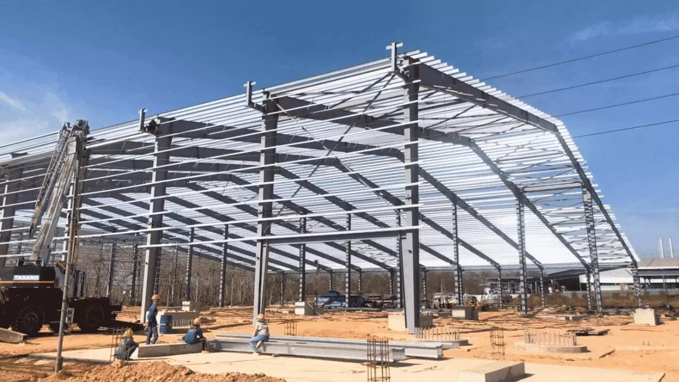
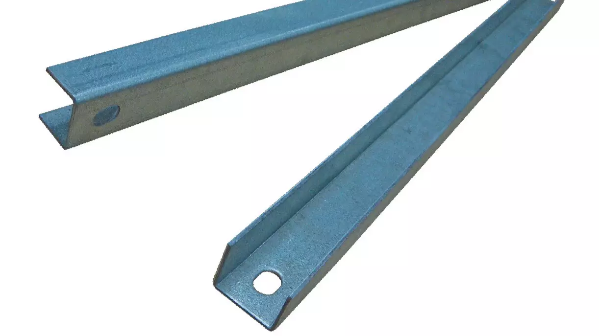
The foundation beam steel structure transmits gravity, ensuring force distribution
2. Structure of steel beam foundation
2.1. Single-beam foundation
A single-beam foundation is a cylindrical reinforced concrete element that connects isolated footings, creating a solid foundation frame. This type of beam comprises a system of reinforcement bars and an encapsulating concrete layer, mainly supporting residential structures (one-story houses, two-story houses, three-story houses), light industrial buildings, and auxiliary structures with moderate and small loads.
The dimensions of a single-beam foundation depend on the load of the structure, geological conditions, and the distance between isolated footings.
Advantages: Simple construction, cost-saving, suitable for good soil conditions. However, its load-bearing capacity is limited, making it unsuitable for weak soil or heavy load structures.
2.2. Mat foundation beam
A mat foundation beam is commonly used in construction, especially for structures with heavy loads or weak soil. This type of beam has a flat structure, spreading across the entire area of the structure, helping to evenly distribute the load onto the soil, reducing the risk of settlement and tilting.
2.3. Strip foundation beam
A strip foundation beam is widely used in construction to connect isolated footings, forming a solid foundation frame for the structure. It has a distinctive structure suitable for various types of buildings and geological conditions. The strip foundation beam consists of the following layers:
- Concrete bedding layer: applied first to create a flat surface for the upper layers.
- Reinforcement system: Consists of two layers:
- Upper reinforcement layer: Mainly withstands compression, usually with larger diameter bars.
- Lower reinforcement layer: Resists tension, connects longitudinal bars, and ensures the beam’s stability.
- Concrete layer: The concrete layer fully encases the entire reinforcement system, protecting the reinforcement from environmental factors and providing compressive strength.
3. Principles for arranging steel beam foundations
3.1. Principles for arranging the steel structure of beam foundations in cross-section
Step 1: Selection of the diameter of the longitudinal reinforcement in the beam
The selection of the diameter of the longitudinal reinforcement in the beam is the most important step to ensure the load-bearing capacity of the entire structure.
Step 2: Protective layer for beam reinforcement
The protective layer for beam reinforcement must distinguish between primary reinforcement (C1) and secondary reinforcement (C2).
Step 3: Spacing of beam reinforcement
The spacing of beam reinforcement is the clear distance between reinforcement parts, and its size must not be smaller than the largest diameter of the reinforcement.
Step 4: Arrangement of intersecting beam reinforcement
The arrangement of intersecting beam reinforcement must follow the principle of placing floor beam reinforcement in two rows to avoid interference. The floor beams and main beams should form a perpendicular point to ensure the structure’s stability and load-bearing efficiency.
3.2. Principles for arranging the steel structure of beam foundations in longitudinal section
General principles for arranging reinforcement in beams
The negative moment reinforcement (tension reinforcement) is placed at the top, while the positive moment reinforcement is placed at the bottom. Within the calculated area, the reinforcement is selected and arranged at the cross-section with the maximum moment.
When cutting and bending the reinforcement, it must be ensured that the remaining steel has the capacity to resist the bending moment not only on the perpendicular cross-section, but also on the inclined cross-sections. The ends of each load-bearing reinforcement bar must also be securely anchored to ensure safety.
Principles for arranging independent column reinforcement
For independent column steel, the placement and arrangement of each span and each support should be done using straight bars to provide flexibility in the selection and arrangement of the reinforcement. Independent reinforcement are straight bars that can be bent at the ends to form inclined reinforcement.
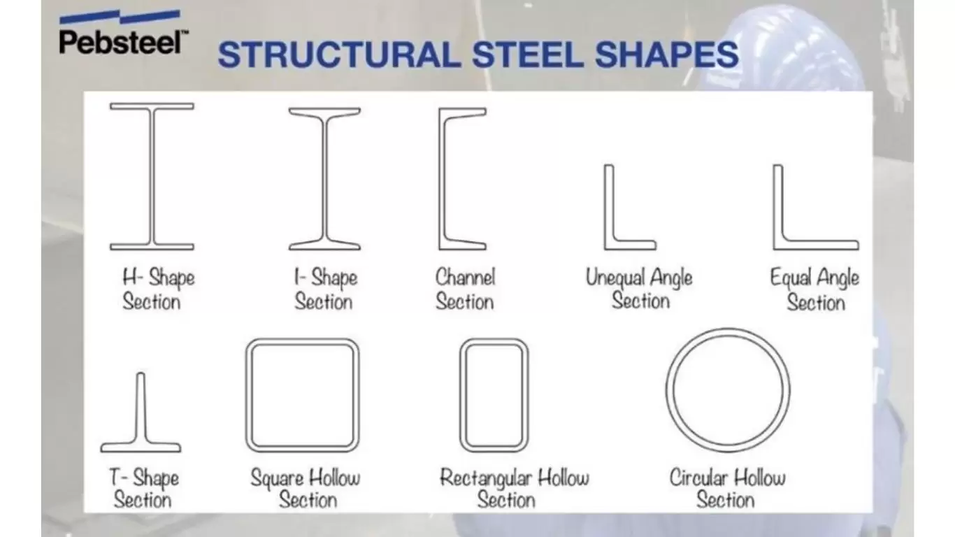
The inclined steel bars are arranged based on the shear force requirements, and can also be long inclined bars to form anchorage segments as per the structural design. The arrangement of steel in independent beams may vary in the number of steel bars at the midspan, side spans, and over the supports, depending on the specific requirements of each project. The materials used to construct the beams are all structural steel. This ensures the quality of pre-engineered steel buildings is guaranteed.

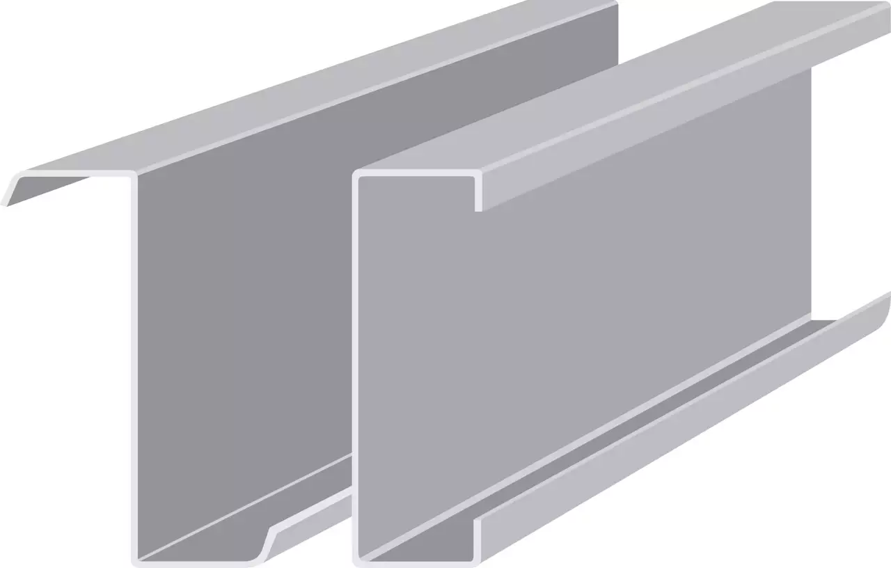
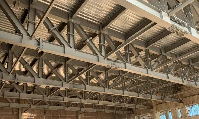
Principles for arranging steel beam foundations
4. Role of beam foundations in steel structures
4.1. Even load distribution and increased stiffness for the foundation system
Beam foundations act as connecting ties, distributing the load from the structure to the foundation evenly, preventing differential settlement and tilting caused by concentrated loads at a single point. This minimizes the risk of foundation damage and protects the upper structures.
Additionally, beam foundations enhance the overall stiffness of the foundation system, improving load-bearing capacity and reducing the risk of cracking due to load impacts and changing geological conditions.
4.2. Prevent differential settlement and stabilize column bases
Connecting isolated footings with beam foundations helps limit differential settlement between footings, ensuring the structure’s balance and preventing tilting and distortion caused by uneven settlement. This protects the upper structures from cracking and damage due to foundation deformation.
Beam foundations also stabilize column bases, ensuring columns remain upright and do not rotate or shift under load impacts. Stabilizing column bases also protects the upper steel structure from collapse due to column instability.
4.3. Creating a unified foundation, waterproofing, and providing a construction surface
Beam foundations connect isolated footings, forming a unified foundation system that acts as a cohesive block. This enhances load-bearing capacity and prevents settlement for the entire structure. A unified foundation helps evenly distribute loads, reducing the risk of cracking and foundation failure due to concentrated loads at a single point.
A unified foundation also helps distribute the loads evenly, minimizing the risk of foundation cracking or failure due to concentrated loads at a single location. Furthermore, the foundation beams have a waterproofing effect on the foundation, protecting the steel structure from corrosion. The foundation beams also create a construction platform for the upper elements, making the construction process easier and safer.
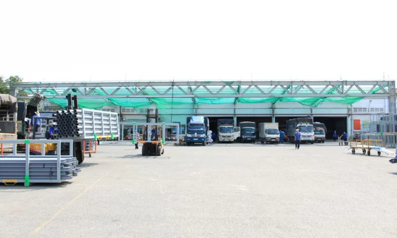
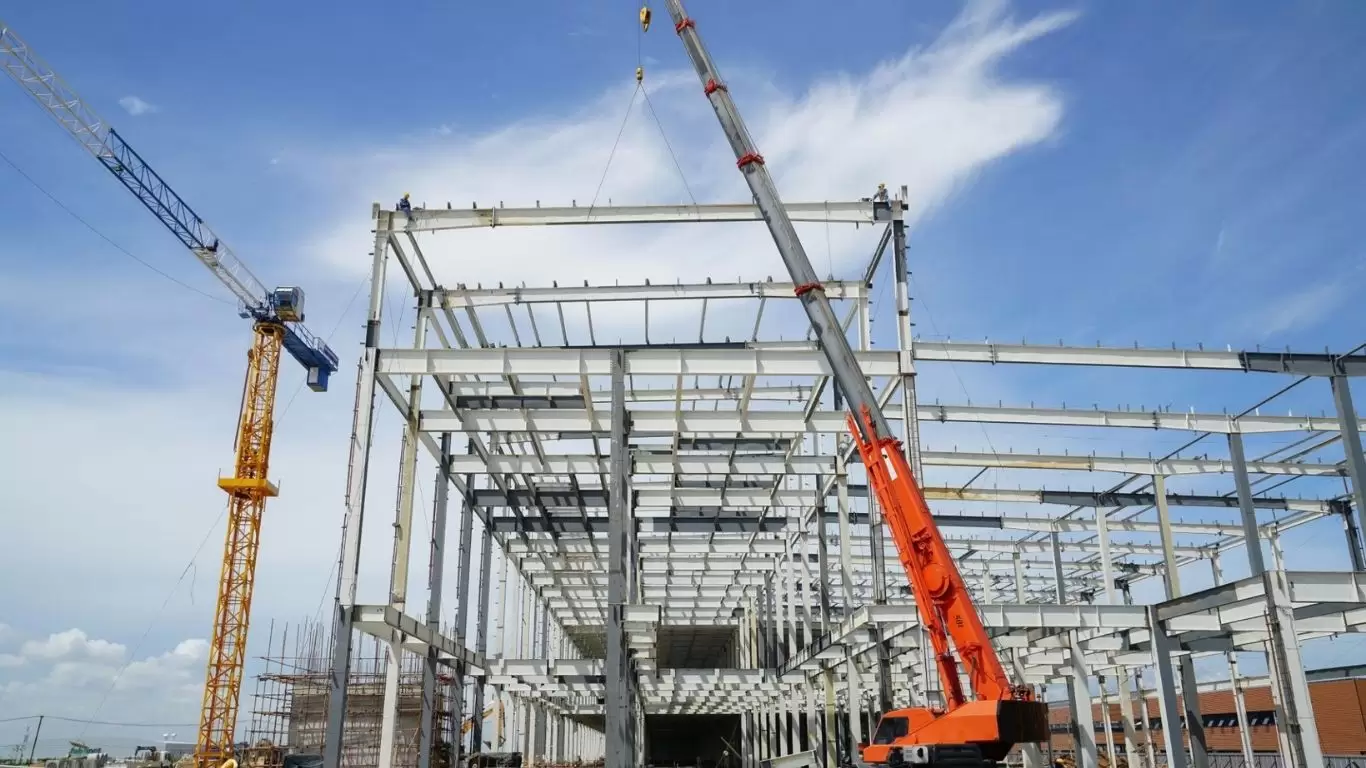
Role of beam foundations in steel structures
Pebsteel, a leading steel structure fabricator in vietnam, will provide you with top-quality, convenient, fast, and efficient structural steel solutions. If you are looking for comprehensive solutions in steel structure construction, contact Pebsteel via email at marketing@pebsteel.com.vn or hotline: at (+84) 908 883 531 for consultation!
*** This article is intended to provide general information about the pre-engineered steel building and steel structure industry only. For further details or clarification based on your needs, please contact Pebsteel directly.